5
GVRP CONFIGURATION GUIDE
Configuring GVRP | GVRP enables a switch to propagate local VLAN registration information to other | ||||
| participant switches and dynamically update the VLAN registration information | ||||
| from other switches to its local database about active VLAN members and through | ||||
| which port they can be reached. GVRP ensures that all switches on a bridged LAN | ||||
| maintain the same VLAN registration information, while less manual configuration | ||||
| workload is involved. |
|
|
| |
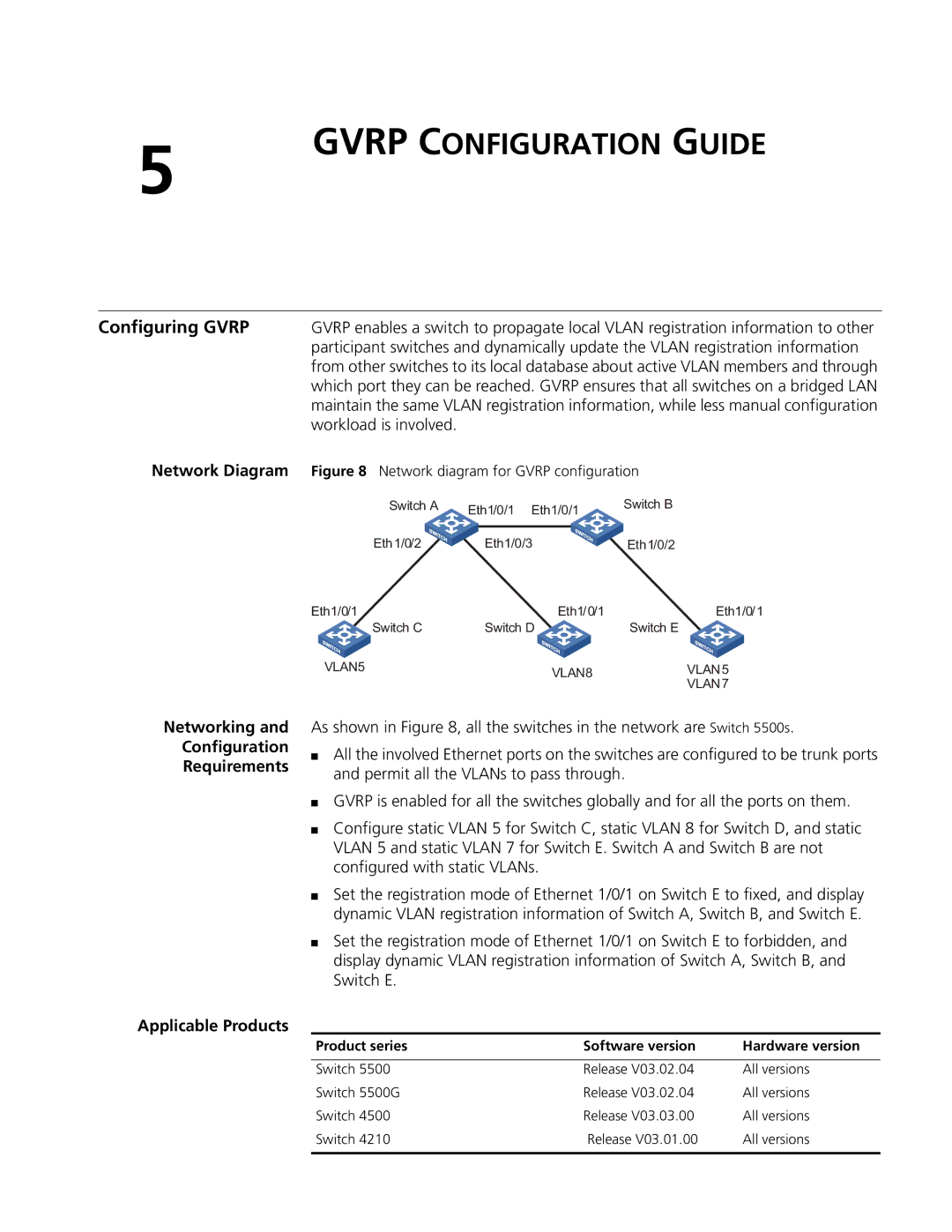
Network Diagram | Figure 8 Network diagram for GVRP configuration | ||||
| Switch A | Eth1/0/1 Eth1/0/1 | Switch B | ||
|
|
|
| ||
|
|
|
|
|
|
| Eth1/0/2 | Eth1/0/3 | Eth1/0/2 | ||
| Eth1/0/1 | Eth1/0/1 | Eth1/0/1 | ||
| Switch C | Switch D | Switch E | ||
| VLAN5 | VLAN8 | VLAN5 | ||
|
|
|
|
| VLAN7 |
Networking and
Configuration
Requirements
As shown in Figure 8, all the switches in the network are Switch 5500s.
■All the involved Ethernet ports on the switches are configured to be trunk ports and permit all the VLANs to pass through.
■GVRP is enabled for all the switches globally and for all the ports on them.
■Configure static VLAN 5 for Switch C, static VLAN 8 for Switch D, and static VLAN 5 and static VLAN 7 for Switch E. Switch A and Switch B are not configured with static VLANs.
■Set the registration mode of Ethernet 1/0/1 on Switch E to fixed, and display dynamic VLAN registration information of Switch A, Switch B, and Switch E.
■Set the registration mode of Ethernet 1/0/1 on Switch E to forbidden, and display dynamic VLAN registration information of Switch A, Switch B, and Switch E.
Applicable Products
Product series | Software version | Hardware version |
|
|
|
Switch 5500 | Release V03.02.04 | All versions |
Switch 5500G | Release V03.02.04 | All versions |
Switch 4500 | Release V03.03.00 | All versions |
Switch 4210 | Release V03.01.00 | All versions |
|
|
|
