DHCP Accounting Configuration Guide 203
Precautions ■ You need to specify the port connected to the authorized DHCP server as a trusted port to ensure that DHCP clients can obtain valid IP addresses. The trusted port and the ports connected to the DHCP clients must be in the same VLAN.
■To enable DHCP snooping on a Switch 5500 that belongs to an XRN fabric, you need to set the fabric ports on all devices in the fabric to DHCP snooping trusted ports to ensure that the clients connected to each device can obtain IP addresses.
■You are not recommended to configure both the DHCP client/BOOTP client and DHCP snooping on the same device; otherwise, the switch may fail to record DHCP snooping entries.
DHCP Accounting | DHCP accounting allows a DHCP server to notify the RADIUS server of the | |||||
Configuration Guide | start/end of accounting when it assigns/releases a lease. The cooperation of the | |||||
| DHCP server and RADIUS server implements the network accounting function and | |||||
| ensures network security at the same time. |
|
| |||
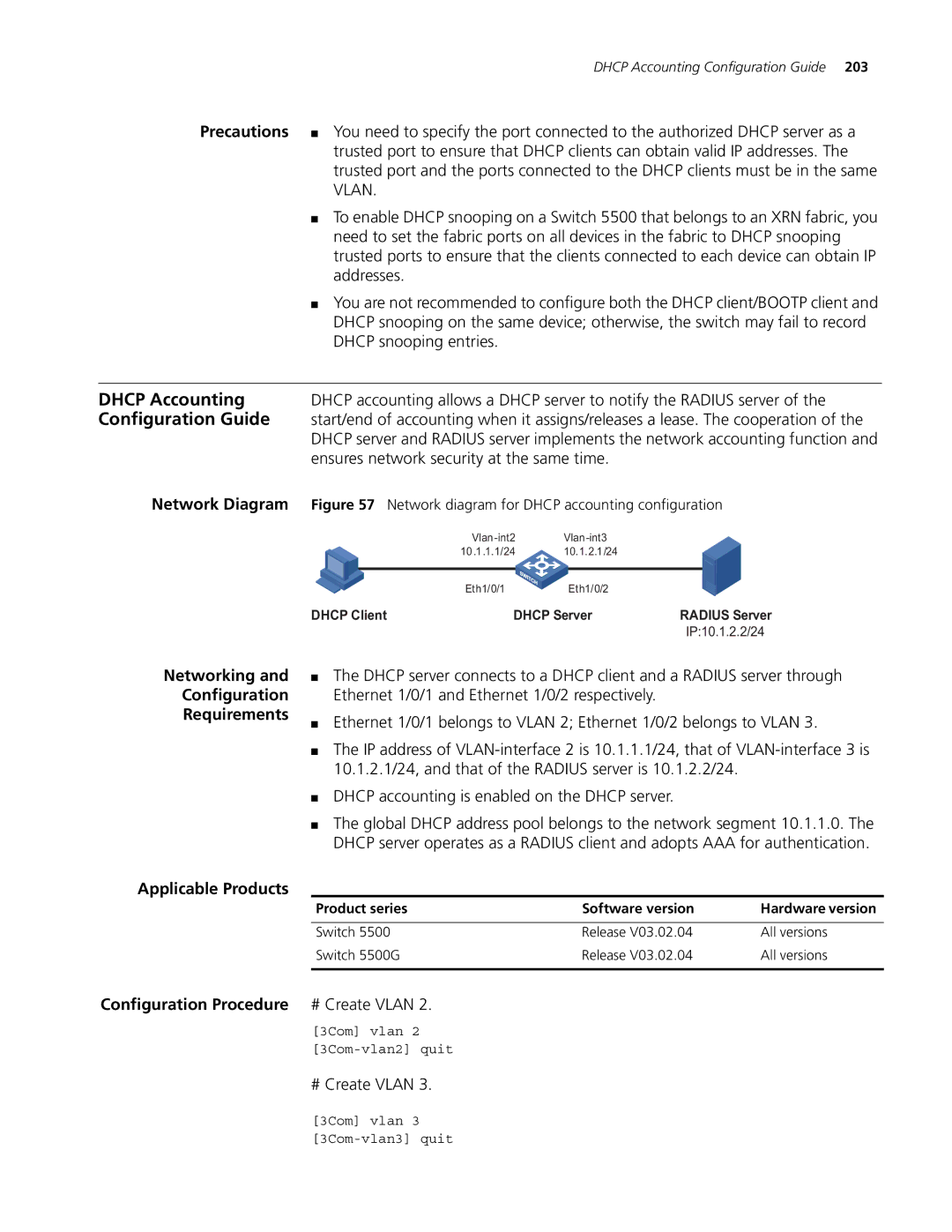
Network Diagram | Figure 57 Network diagram for DHCP accounting configuration | |||||
|
|
|
|
| ||
|
|
| 10.1.1.1/24 | 10.1.2.1/24 |
|
|
|
|
|
|
|
|
|
|
|
| Eth1/0/1 | Eth1/0/2 |
|
|
| DHCP Client | DHCP Server | RADIUS Server | |||
|
|
|
|
| IP:10.1.2.2/24 | |
Networking and
Configuration
Requirements
■The DHCP server connects to a DHCP client and a RADIUS server through Ethernet 1/0/1 and Ethernet 1/0/2 respectively.
■Ethernet 1/0/1 belongs to VLAN 2; Ethernet 1/0/2 belongs to VLAN 3.
■The IP address of
■DHCP accounting is enabled on the DHCP server.
■The global DHCP address pool belongs to the network segment 10.1.1.0. The DHCP server operates as a RADIUS client and adopts AAA for authentication.
Applicable Products
Product series | Software version | Hardware version |
|
|
|
Switch 5500 | Release V03.02.04 | All versions |
Switch 5500G | Release V03.02.04 | All versions |
|
|
|
Configuration Procedure # Create VLAN 2.
[3Com] vlan 2
# Create VLAN 3.
[3Com] vlan 3