PORT ISOLATION CONFIGURATION
8 GUIDE
Configuring Port | Port isolation allows you to add a port into an isolation group to isolate |
Isolation | and |
| While increasing network security, this allows for great flexibility. |
| Currently, the Switch 5500 supports only one isolation group; however, the |
| number of Ethernet ports in the isolation group is not limited. |
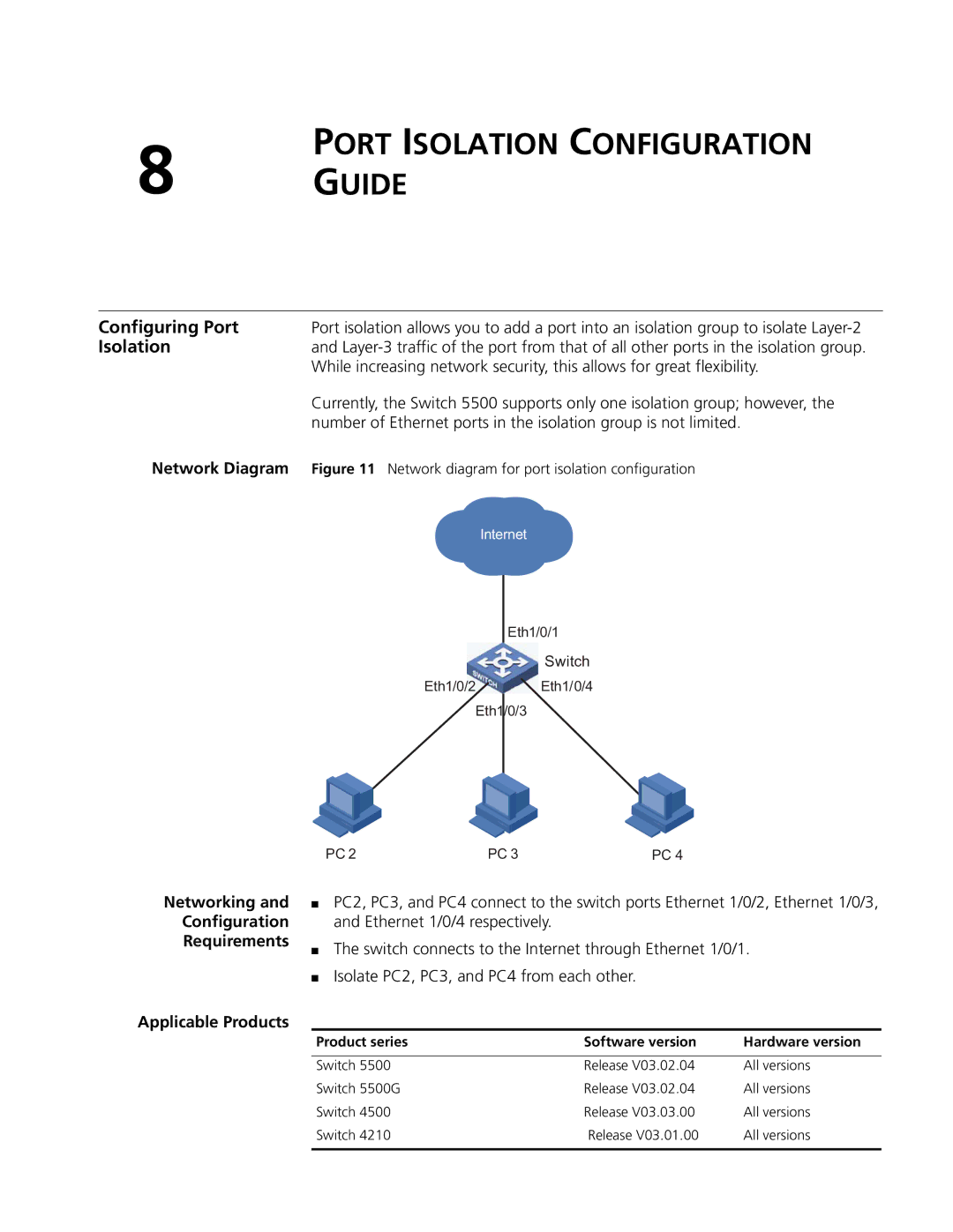
Network Diagram | Figure 11 Network diagram for port isolation configuration |
| Internet |
Eth1/0/1
Switch
Eth1/0/2 | Eth1/0/4 |
Eth1/0/3
PC 2 | PC 3 | PC 4 |
Networking and
Configuration
Requirements
Applicable Products
■PC2, PC3, and PC4 connect to the switch ports Ethernet 1/0/2, Ethernet 1/0/3, and Ethernet 1/0/4 respectively.
■The switch connects to the Internet through Ethernet 1/0/1.
■Isolate PC2, PC3, and PC4 from each other.
Product series | Software version | Hardware version |
|
|
|
Switch 5500 | Release V03.02.04 | All versions |
Switch 5500G | Release V03.02.04 | All versions |
Switch 4500 | Release V03.03.00 | All versions |
Switch 4210 | Release V03.01.00 | All versions |
|
|
|