252CHAPTER 27: CLUSTER CONFIGURATION GUIDE
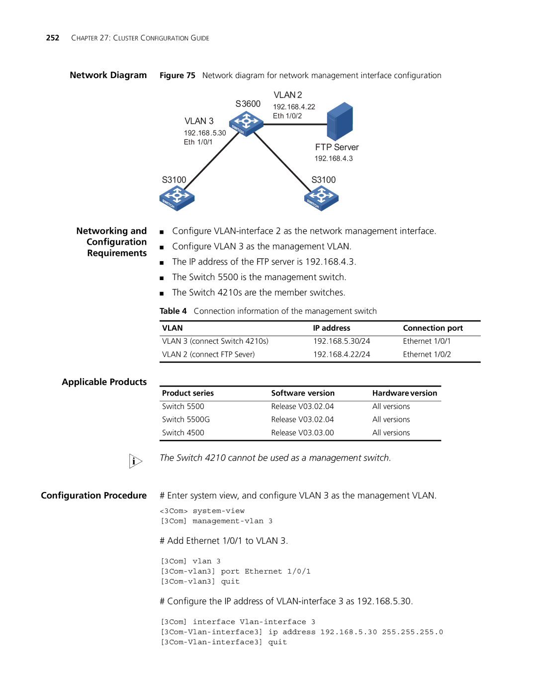
Network Diagram Figure 75 Network diagram for network management interface configuration
VLAN 2
S3600 192.168.4.22
VLAN 3
Eth 1/0/2
192.168.5.30 Eth 1/0/1
FTP Server
192.168.4.3
S3100 | S3100 |
Networking and
Configuration
Requirements
Applicable Products
■Configure
■Configure VLAN 3 as the management VLAN.
■The IP address of the FTP server is 192.168.4.3.
■The Switch 5500 is the management switch.
■The Switch 4210s are the member switches.
Table 4 Connection information of the management switch
VLAN |
| IP address | Connection port |
|
|
|
|
VLAN 3 | (connect Switch 4210s) | 192.168.5.30/24 | Ethernet 1/0/1 |
VLAN 2 | (connect FTP Sever) | 192.168.4.22/24 | Ethernet 1/0/2 |
|
|
|
|
Product series | Software version | Hardware version |
|
|
|
Switch 5500 | Release V03.02.04 | All versions |
Switch 5500G | Release V03.02.04 | All versions |
Switch 4500 | Release V03.03.00 | All versions |
|
|
|
n The Switch 4210 cannot be used as a management switch.
Configuration Procedure # Enter system view, and configure VLAN 3 as the management VLAN.
<3Com>
[3Com]
# Add Ethernet 1/0/1 to VLAN 3.
[3Com] vlan 3
# Configure the IP address of VLAN-interface 3 as 192.168.5.30.
[3Com] interface