78CHAPTER 14: MSTP CONFIGURATION GUIDE
Applicable Products
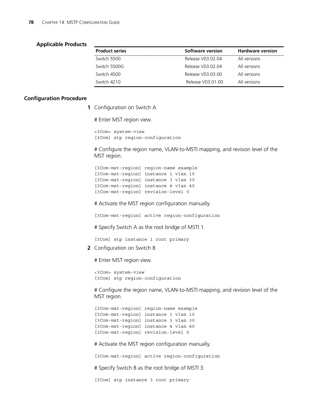
Product series | Software version | Hardware version |
|
|
|
Switch 5500 | Release V03.02.04 | All versions |
Switch 5500G | Release V03.02.04 | All versions |
Switch 4500 | Release V03.03.00 | All versions |
Switch 4210 | Release V03.01.00 | All versions |
|
|
|
Configuration Procedure
1Configuration on Switch A
# Enter MST region view.
<3Com>
[3Com] stp
#Configure the region name,
# Activate the MST region configuration manually.
# Specify Switch A as the root bridge of MSTI 1.
[3Com] stp instance 1 root primary
2Configuration on Switch B
# Enter MST region view.
<3Com>
[3Com] stp
#Configure the region name,
# Activate the MST region configuration manually.
# Specify Switch B as the root bridge of MSTI 3.
[3Com] stp instance 3 root primary