236CHAPTER 25: MIRRORING CONFIGURATION GUIDE
■Packets received on the destination port are those processed and forwarded by the switch.
■The destination port to be configured cannot be a member port of an existing mirroring group; a fabric port (only the Switch 5500/5500G have this limitation), a member port of an aggregation group, an LACP enabled port, or an STP enabled port.
■Only an existing static VLAN can be configured as the
Traffic Mirroring | In traffic mirroring, an ACL is applied to a port to identify traffics. Packets passing |
Configuration | through the port and matching the ACL rules are mirrored to the destination port. |
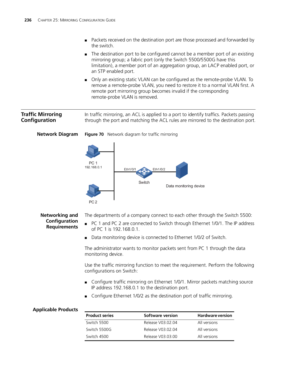
Network Diagram | Figure 70 Network diagram for traffic mirroring |
PC 1
192.168.0.1
PC 2
Eth1/0/1 Eth1/0/2
Switch
Data monitoring device
Networking and
Configuration
Requirements
The departments of a company connect to each other through the Switch 5500:
■PC 1 and PC 2 are connected to Switch through Ethernet 1/0/1. The IP address of PC 1 is 192.168.0.1.
■Data monitoring device is connected to Ethernet 1/0/2 of Switch.
The administrator wants to monitor packets sent from PC 1 through the data monitoring device.
Use the traffic mirroring function to meet the requirement. Perform the following configurations on Switch:
■Configure traffic mirroring on Ethernet 1/0/1. Mirror packets matching source IP address 192.168.0.1 to the destination port.
■Configure Ethernet 1/0/2 as the destination port of traffic mirroring.
Applicable Products
Product series | Software version | Hardware version |
|
|
|
Switch 5500 | Release V03.02.04 | All versions |
Switch 5500G | Release V03.02.04 | All versions |
Switch 4500 | Release V03.03.00 | All versions |
|
|
|