NTP Broadcast Mode Configuration 273
# Set Device C as the
<DeviceB>
[DeviceB]
#View NTP status and NTP session information of Device C after clock synchronization.
[DeviceC] display
[DeviceC] display
Complete Configuration ■ Configuration on Device C.
#
■Configuration on Device B.
#
Precautions The local clock of a Switch 5500, 5500G, or 4210 cannot be set as a reference clock. It can synchronize other devices as a reference clock only when its clock is synchronized.
NTP Broadcast Mode
Configuration
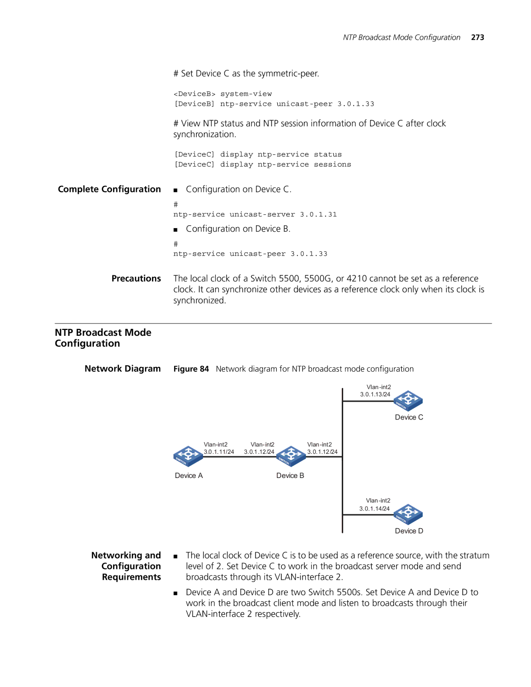
Network Diagram Figure 84 Network diagram for NTP broadcast mode configuration
3.0.1.11/24 | 3.0.1.12/24 | 3.0.1.12/24 |
Device A | Device B |
Device C
| Device D |
Networking and | ■ The local clock of Device C is to be used as a reference source, with the stratum |
Configuration | level of 2. Set Device C to work in the broadcast server mode and send |
Requirements | broadcasts through its |
| ■ Device A and Device D are two Switch 5500s. Set Device A and Device D to |
| work in the broadcast client mode and listen to broadcasts through their |
|