160CHAPTER 16: MULTICAST CONFIGURATION GUIDE
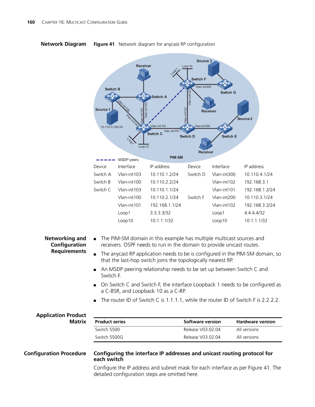
Network Diagram Figure 41 Network diagram for anycast RP configuration
|
|
|
|
|
|
|
| Source 3 |
|
|
| Receiver |
| 1 | Loop10 |
| |||
|
|
|
|
|
|
|
|
| |
|
|
|
|
|
| p |
|
|
|
|
|
|
|
| o |
|
|
| |
|
|
|
| o |
|
|
|
| |
|
|
|
| L |
|
|
|
|
|
|
|
|
|
|
|
|
| Switch F |
|
Switch B |
|
|
|
|
|
|
| ||
|
|
|
|
|
| 02 | Switch G | ||
|
|
|
|
|
|
|
| ||
|
|
|
| Switch A |
|
|
| nt1 | |
|
|
|
|
|
|
|
| ||
| V |
|
|
|
|
|
| ||
|
|
|
|
|
|
|
| ||
| l |
|
|
|
|
|
|
| |
| a |
|
|
|
| ||||
| 1 |
|
|
|
| ||||
| n |
|
|
|
|
|
|
|
|
| - |
|
|
|
|
|
|
|
|
| i |
|
|
|
|
|
|
|
|
| n |
|
|
|
|
|
|
|
|
| t |
|
|
|
|
|
|
|
|
Source 1 | 1 |
|
|
|
|
|
|
|
|
0 |
|
|
|
|
|
|
|
| |
| 0 |
|
|
|
|
|
| Receiver |
|
| V |
|
|
|
|
|
|
| |
| l |
|
|
|
|
|
|
|
|
| a |
|
|
|
|
|
|
| Source 2 |
| n |
|
|
|
|
|
|
| |
| n |
|
|
|
|
|
|
|
|
| - |
|
|
|
|
|
|
|
|
| i |
|
|
|
|
|
|
|
|
| t |
|
|
|
|
|
|
|
|
| 00 |
|
|
|
|
| |||
10.110.5.100/24 |
|
|
|
|
|
| |||
|
|
|
|
|
|
|
| ||
|
|
|
|
|
|
| |||
|
|
|
| Switch C |
|
| Switch D | Switch E | |
| Lo |
|
|
|
|
| |||
|
|
|
|
|
|
|
|
| |
| o |
|
|
|
|
|
|
|
|
| p1 |
|
|
|
|
|
|
|
|
|
|
| Loop10 |
|
|
|
|
| |
|
|
|
|
|
|
|
| Receiver |
|
| MSDP peers |
|
|
| |
|
|
|
|
| |
Device | Interface | IP address | Device | Interface | IP address |
Switch A | 10.110.1.2/24 | Switch D | 10.110.4.1/24 | ||
Switch B | 10.110.2.2/24 |
| 192.168.3.1 | ||
Switch C | 10.110.1.1/24 |
| 192.168.1.2/24 | ||
| 10.110.2.1/24 | Switch F | 10.110.3.1/24 | ||
| 192.168.1.1/24 |
| 192.168.3.2/24 | ||
| Loop1 | 3.3.3.3/32 |
| Loop1 | 4.4.4.4/32 |
| Loop10 | 10.1.1.1/32 |
| Loop10 | 10.1.1.1/32 |
Networking and
Configuration
Requirements
Application Product Matrix
■The
■The anycast RP application needs to be is configured in the
■An MSDP peering relationship needs to be set up between Switch C and Switch F.
■On Switch C and Switch F, the interface Loopback 1 needs to be configured as a
■The router ID of Switch C is 1.1.1.1, while the router ID of Switch F is 2.2.2.2.
Product series | Software version | Hardware version |
|
|
|
Switch 5500 | Release V03.02.04 | All versions |
Switch 5500G | Release V03.02.04 | All versions |
|
|
|
Configuration Procedure Configuring the interface IP addresses and unicast routing protocol for each switch
Configure the IP address and subnet mask for each interface as per Figure 41. The detailed configuration steps are omitted here.