25
MIRRORING CONFIGURATION GUIDE
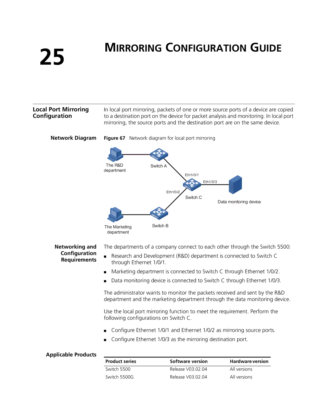
Local Port Mirroring In local port mirroring, packets of one or more source ports of a device are copied
Configuration to a destination port on the device for packet analysis and monitoring. In local port mirroring, the source ports and the destination port are on the same device.
Network Diagram Figure 67 Network diagram for local port mirroring
Networking and
Configuration
Requirements
The R&D | Switch A |
department |
|
Eth1/0/1
Eth1/0/3
Eth1/0/2
Switch C
Data monitoring device
The Marketing | Switch B |
department |
|
The departments of a company connect to each other through the Switch 5500:
■Research and Development (R&D) department is connected to Switch C through Ethernet 1/0/1.
■Marketing department is connected to Switch C through Ethernet 1/0/2.
■Data monitoring device is connected to Switch C through Ethernet 1/0/3.
The administrator wants to monitor the packets received and sent by the R&D department and the marketing department through the data monitoring device.
Use the local port mirroring function to meet the requirement. Perform the following configurations on Switch C.
■Configure Ethernet 1/0/1 and Ethernet 1/0/2 as mirroring source ports.
■Configure Ethernet 1/0/3 as the mirroring destination port.
Applicable Products
Product series | Software version | Hardware version |
|
|
|
Switch 5500 | Release V03.02.04 | All versions |
Switch 5500G | Release V03.02.04 | All versions |