2
VLAN CONFIGURATION GUIDE
Configuring | The VLAN technology allows you to divide a broadcast LAN into multiple distinct |
| broadcast domains, each as a virtual workgroup. |
| approach to VLAN implementation. The idea is to assign the ports on a switch to |
| different VLANs, confining the propagation of the packets received on a port |
| within the particular VLAN. Thus, separation of broadcast domains and division of |
| virtual groups are achieved. |
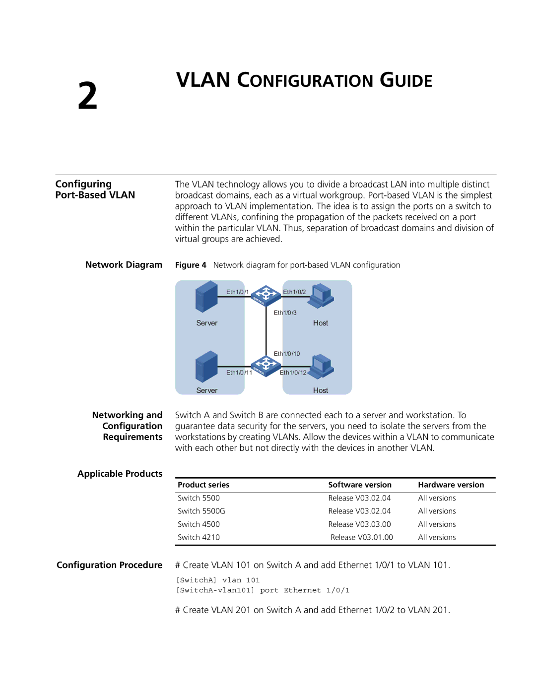
Network Diagram | Figure 4 Network diagram for |
| Eth1/0/1 | Eth1/0/2 |
|
|
| Eth1/0 /3 | |
Server |
| Host | |
Eth1/0 /10
Eth1/0/11 ![]()
![]()
![]()
![]()
![]() Eth1/0/12
Eth1/0/12![]()
![]()
Server | Host |
Networking and Switch A and Switch B are connected each to a server and workstation. To Configuration guarantee data security for the servers, you need to isolate the servers from the Requirements workstations by creating VLANs. Allow the devices within a VLAN to communicate
with each other but not directly with the devices in another VLAN.
Applicable Products
Product series | Software version | Hardware version |
|
|
|
Switch 5500 | Release V03.02.04 | All versions |
Switch 5500G | Release V03.02.04 | All versions |
Switch 4500 | Release V03.03.00 | All versions |
Switch 4210 | Release V03.01.00 | All versions |
|
|
|
Configuration Procedure # Create VLAN 101 on Switch A and add Ethernet 1/0/1 to VLAN 101.
[SwitchA] vlan 101
# Create VLAN 201 on Switch A and add Ethernet 1/0/2 to VLAN 201.
