186CHAPTER 20: VRRP CONFIGURATION GUIDE
■If both switches in the preemptive mode and switches in the
Multiple VRRP Groups Multiple VRRP groups can implement the link backup and load sharing functions,
Configuration which can avoid communication interruption resulting from switch failure or traffic overburden on a link.
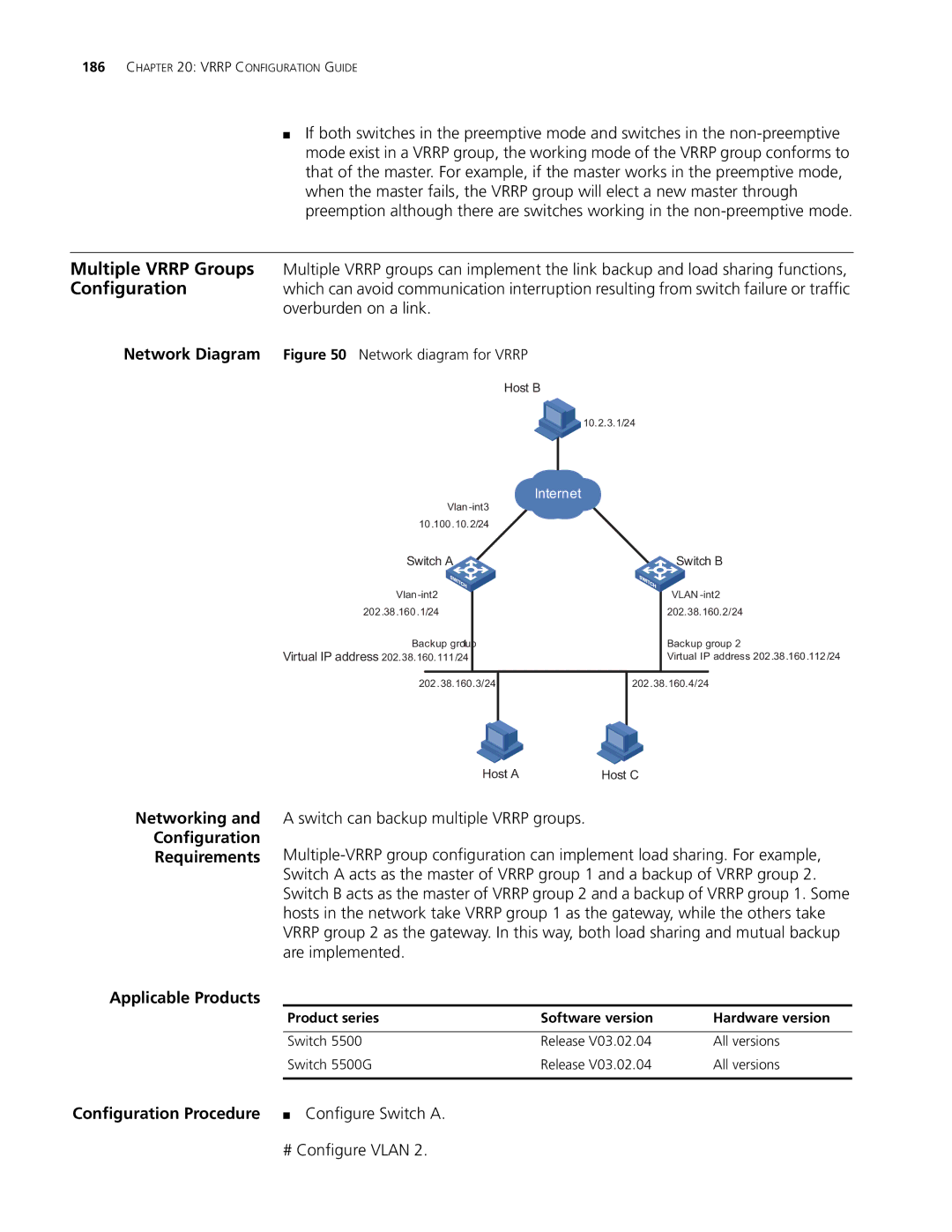
Network Diagram Figure 50 Network diagram for VRRP
Host B
![]()
![]()
![]() 10.2.3.1/24
10.2.3.1/24
Internet
10 .100.10.2/24
Switch A![]()
202.38.160.1/24
Backup group1
Virtual IP address 202.38.160.111/24
Switch B
VLAN
202.38.160.2/24
Backup group 2
Virtual IP address 202.38 .160.112/24
202.38.160.3/24
202.38.160.4/24
Networking and
Configuration
Requirements
Applicable Products
Host A | Host C |
A switch can backup multiple VRRP groups.
Product series | Software version | Hardware version |
|
|
|
Switch 5500 | Release V03.02.04 | All versions |
Switch 5500G | Release V03.02.04 | All versions |
|
|
|
Configuration Procedure ■ Configure Switch A.
# Configure VLAN 2.