198CHAPTER 21: DHCP CONFIGURATION GUIDE
DHCP Server Interface
Address Pool
Configuration Guide
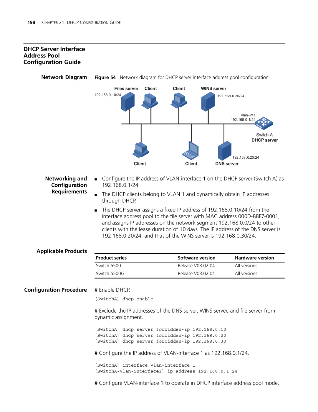
Network Diagram Figure 54 Network diagram for DHCP server interface address pool configuration
Files server Client | Client | WINS server | |||||
192.168.0.10/24 |
|
|
|
|
| 192.168.0.30/24 | |
|
|
|
|
|
| ||
|
|
|
|
|
|
| |
|
|
|
|
|
|
| |
|
|
|
|
|
|
| |
|
|
|
|
|
|
| 192.168.0.1/24 |
|
|
|
|
|
|
|
|
Networking and
Configuration
Requirements
Switch A
DHCP server
192.168.0.20/24
Client | Client | DNS server |
■Configure the IP address of
■The DHCP clients belong to VLAN 1 and dynamically obtain IP addresses through DHCP.
■The DHCP server assigns a fixed IP address of 192.168.0.10/24 from the interface address pool to the file server with MAC address
Applicable Products
Product series | Software version | Hardware version |
|
|
|
Switch 5500 | Release V03.02.04 | All versions |
Switch 5500G | Release V03.02.04 | All versions |
|
|
|
Configuration Procedure # Enable DHCP.
[SwitchA] dhcp enable
#Exclude the IP addresses of the DNS server, WINS server, and file server from dynamic assignment.
[SwitchA] dhcp server
[SwitchA] dhcp server
[SwitchA] dhcp server
# Configure the IP address of
[SwitchA] interface
# Configure