Configuring Routing Policies 129
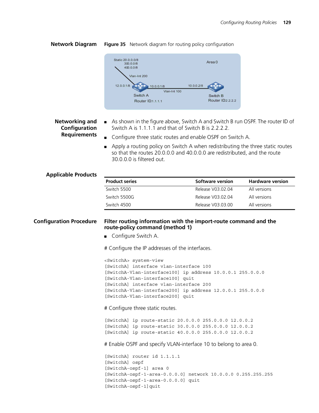
Network Diagram Figure 35 Network diagram for routing policy configuration
Static 20 .0.0.0/8 |
| Area 0 | ||
30.0.0.0/8 |
|
| ||
|
|
|
| |
40.0.0.0/8 |
|
|
|
|
Vlan |
|
|
| |
12.0.0.1/8 |
| 10.0.0.1/8 | 10.0.0 .2/8 |
|
Switch A |
|
| ||
| Switch B | |||
Router ID:1 .1.1.1 | Router ID:2 .2.2.2 | |||
Networking and
Configuration
Requirements
■As shown in the figure above, Switch A and Switch B run OSPF. The router ID of Switch A is 1.1.1.1 and that of Switch B is 2.2.2.2.
■Configure three static routes and enable OSPF on Switch A.
■Apply a routing policy on Switch A when redistributing the three static routes so that the routes 20.0.0.0 and 40.0.0.0 are redistributed, and the route 30.0.0.0 is filtered out.
Applicable Products
Product series | Software version | Hardware version |
|
|
|
Switch 5500 | Release V03.02.04 | All versions |
Switch 5500G | Release V03.02.04 | All versions |
Switch 4500 | Release V03.03.00 | All versions |
|
|
|
Configuration Procedure Filter routing information with the
■Configure Switch A.
# Configure the IP addresses of the interfaces.
<SwitchA>
[SwitchA] interface
# Configure three static routes.
[SwitchA] ip
[SwitchA] ip
[SwitchA] ip
# Enable OSPF and specify
[SwitchA] router id 1.1.1.1
[SwitchA] ospf