126CHAPTER 15: ROUTING CONFIGURATION GUIDE
Configuring OSPF | Among OSPF areas in an AS, one area is different from any other area. Its area ID is | |||||
Virtual Link | 0 and it is usually called the backbone area. The backbone area is responsible for | |||||
| distributing routing information between | |||||
| requires that: |
|
|
| ||
| ■ All | |||||
| ■ The backbone area must maintain connectivity within itself. |
| ||||
| In practice, the requirements may not be satisfied due to physical limitations. In | |||||
| this case, configuring OSPF virtual links is a solution. |
| ||||
| A virtual link is established between two ABRs through a | |||||
| is configured on both ABRs to take effect. The | |||||
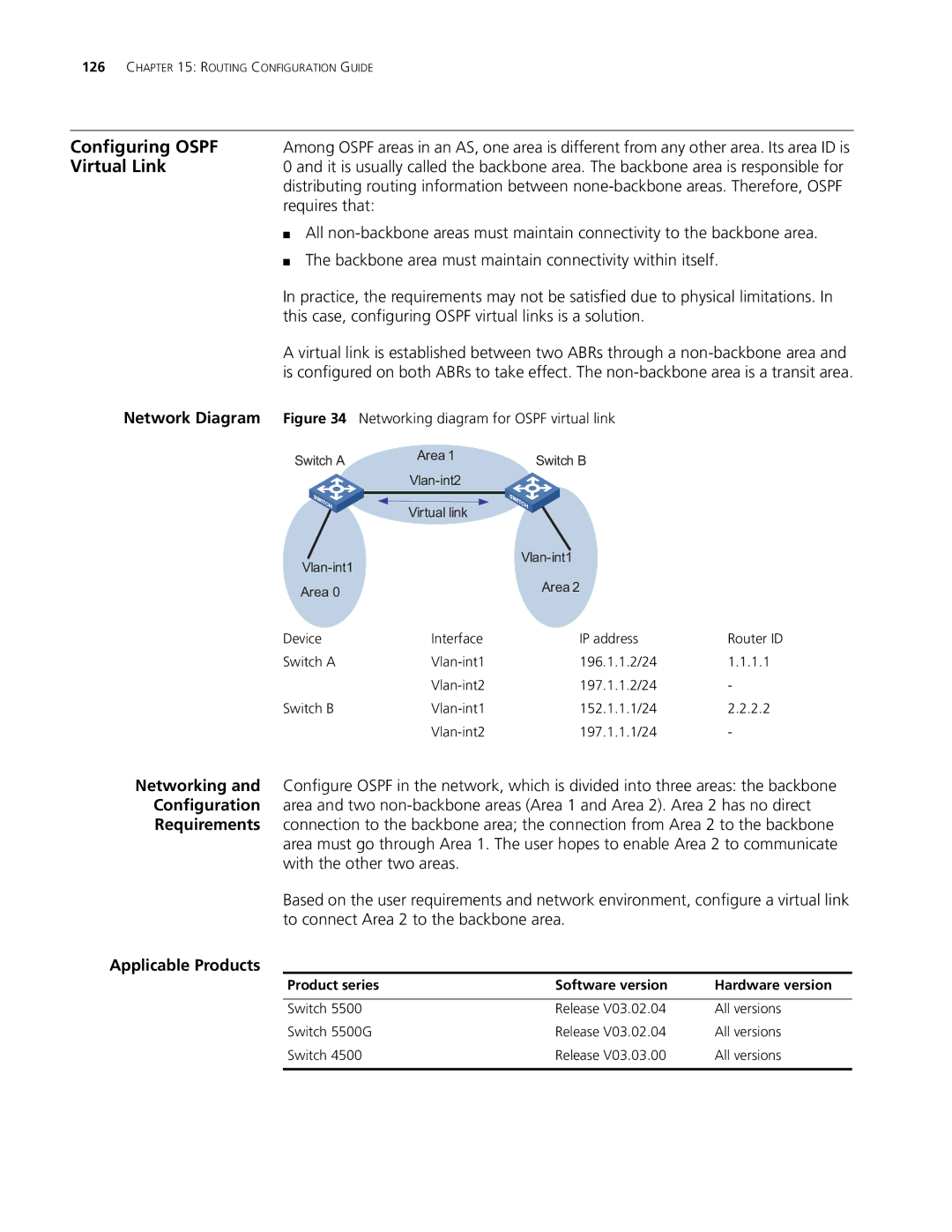
Network Diagram | Figure 34 | Networking diagram for OSPF virtual link |
| |||
| Switch A | Area 1 |
| Switch B |
| |
|
|
|
| |||
|
|
|
|
|
| |
|
|
|
|
|
|
|
|
|
| Virtual link |
|
|
|
|
|
|
| |||
|
|
|
|
| ||
| Area 0 |
|
| Area 2 |
| |
|
|
|
|
| ||
| Device | Interface |
| IP address | Router ID | |
| Switch A | 196.1.1.2/24 | 1.1.1.1 | |||
|
|
| 197.1.1.2/24 | - | ||
| Switch B | 152.1.1.1/24 | 2.2.2.2 | |||
|
|
| 197.1.1.1/24 | - | ||
Networking and Configure OSPF in the network, which is divided into three areas: the backbone Configuration area and two
area must go through Area 1. The user hopes to enable Area 2 to communicate with the other two areas.
Based on the user requirements and network environment, configure a virtual link to connect Area 2 to the backbone area.
Applicable Products
Product series | Software version | Hardware version |
|
|
|
Switch 5500 | Release V03.02.04 | All versions |
Switch 5500G | Release V03.02.04 | All versions |
Switch 4500 | Release V03.03.00 | All versions |
|
|
|