35
VLAN-VPN CONFIGURATION GUIDE
Configuring | With |
| VLAN tag, thus enabling the packet to be transmitted through the service |
| providers’ backbone network with both inner and outer VLAN tags. After reaching |
| the peer private network, the packet’s outer VLAN tag will be removed and the |
| inner tag will be used for packet forwarding. |
| |
| simple way. |
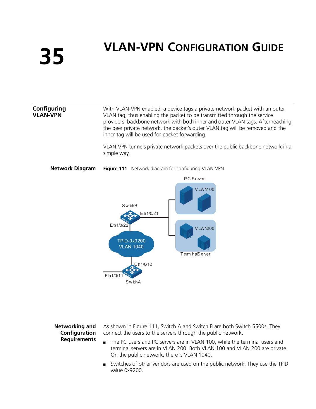
Network Diagram | Figure 111 Network diagram for configuring |
| PC Server |
| VLAN100 |
S w tchBi
E th1/0/21
E th1/0/22
VLAN 1040
E th1/0/12
E th1/0/11![]()
![]()
S w ichAt
![]()
![]() VLAN200
VLAN200
Term inalServer
Networking and
Configuration
Requirements
As shown in Figure 111, Switch A and Switch B are both Switch 5500s. They connect the users to the servers through the public network.
■The PC users and PC servers are in VLAN 100, while the terminal users and terminal servers are in VLAN 200. Both VLAN 100 and VLAN 200 are private. On the public network, there is VLAN 1040.
■Switches of other vendors are used on the public network. They use the TPID value 0x9200.