22
ACL CONFIGURATION GUIDE
Configuring Basic | Basic ACLs filter packets based on only source IP address. |
ACLs | The numbers of basic ACLs range from 2000 to 2999. |
| |
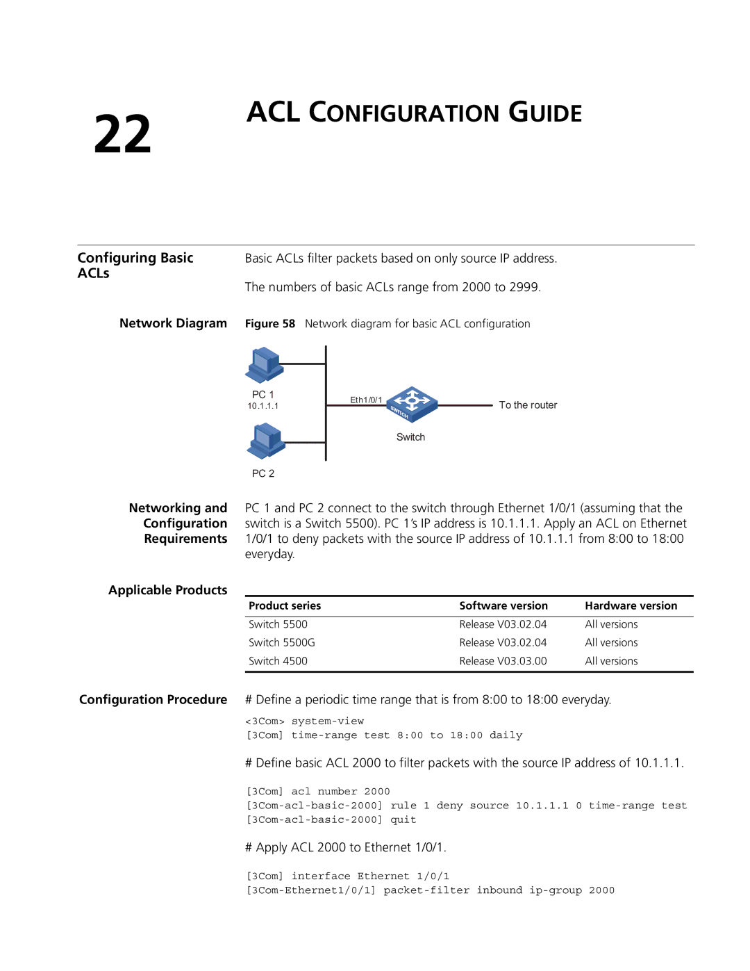
Network Diagram | Figure 58 Network diagram for basic ACL configuration |
PC 1 |
10.1.1.1 |
PC 2
Eth1/0/1
To the router
Switch
Networking and PC 1 and PC 2 connect to the switch through Ethernet 1/0/1 (assuming that the Configuration switch is a Switch 5500). PC 1’s IP address is 10.1.1.1. Apply an ACL on Ethernet Requirements 1/0/1 to deny packets with the source IP address of 10.1.1.1 from 8:00 to 18:00
everyday.
Applicable Products
Product series | Software version | Hardware version |
|
|
|
Switch 5500 | Release V03.02.04 | All versions |
Switch 5500G | Release V03.02.04 | All versions |
Switch 4500 | Release V03.03.00 | All versions |
|
|
|
Configuration Procedure # Define a periodic time range that is from 8:00 to 18:00 everyday.
<3Com>
[3Com]
# Define basic ACL 2000 to filter packets with the source IP address of 10.1.1.1.
[3Com] acl number 2000
# Apply ACL 2000 to Ethernet 1/0/1.
[3Com] interface Ethernet 1/0/1