Configuring PIM-SM plus IGMP plus IGMP Snooping 147
Then, the multicast source sends the multicast traffic along the SPT to the RP. Upon reaching the RP, the multicast traffic flows down the RPT to the receivers.
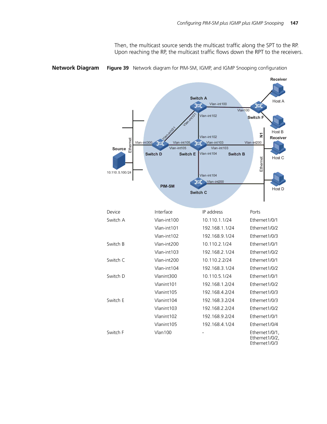
Network Diagram Figure 39 Network diagram for
Receiver
Switch A
Host A
|
|
|
|
|
|
|
|
|
|
|
| |
|
|
|
|
|
|
|
|
|
|
| Vlan100 |
|
|
|
|
|
|
|
|
| 01 |
| Switch F |
| |
|
|
|
|
|
|
|
| t1 |
|
|
| |
|
|
|
|
|
|
| in |
|
|
|
| |
|
|
|
|
|
| - |
|
|
|
|
| |
|
|
|
|
|
| n |
|
|
|
|
|
|
|
|
|
|
|
| la |
|
|
|
|
|
|
|
|
|
|
| 01 | V |
|
|
|
|
|
|
|
|
|
|
|
|
|
|
|
|
| Host B | |
|
|
|
| 1 |
|
|
|
|
| N1 | ||
|
|
|
| int |
|
|
|
|
|
| ||
|
|
| - |
|
|
|
|
|
|
| ||
|
|
| n |
|
|
|
|
|
| Receiver | ||
| Ethernet | la |
|
|
|
|
|
| ||||
|
|
|
|
|
| |||||||
Source |
|
|
|
|
|
|
| |||||
| Switch D |
|
| Switch E | Switch B |
| ||||||
|
|
|
| Host C | ||||||||
|
|
|
|
|
|
|
|
|
|
| Ethernet | |
10.110.5.100/24 |
|
|
|
|
|
|
|
|
|
| ||
|
|
|
|
|
|
|
|
|
| |||
|
|
|
|
|
|
|
|
|
|
|
| |
|
|
|
|
|
|
|
|
| ||||
|
|
|
|
|
|
|
|
| Host D | |||
|
|
|
|
|
|
|
| Switch C |
|
| ||
|
|
|
|
|
|
|
|
|
|
| ||
Device |
|
| Interface |
|
|
| IP address |
| Ports |
| ||
Switch A |
|
|
|
|
| 10.110.1.1/24 | Ethernet1/0/1 | |||||
|
|
|
|
|
| 192.168.1.1/24 | Ethernet1/0/2 | |||||
|
|
|
|
|
| 192.168.9.1/24 | Ethernet1/0/3 | |||||
Switch B |
|
|
|
|
| 10.110.2.1/24 | Ethernet1/0/1 | |||||
|
|
|
|
|
| 192.168.2.1/24 | Ethernet1/0/2 | |||||
Switch C |
|
|
|
|
| 10.110.2.2/24 | Ethernet1/0/1 | |||||
|
|
|
|
|
| 192.168.3.1/24 | Ethernet1/0/2 | |||||
Switch D |
|
| Vlanint300 |
|
|
| 10.110.5.1/24 | Ethernet1/0/1 | ||||
|
|
| Vlanint101 |
|
|
| 192.168.1.2/24 | Ethernet1/0/2 | ||||
|
|
| Vlanint105 |
|
|
| 192.168.4.2/24 | Ethernet1/0/3 | ||||
Switch E |
|
| Vlanint104 |
|
|
| 192.168.3.2/24 | Ethernet1/0/3 | ||||
|
|
| Vlanint103 |
|
|
| 192.168.2.2/24 | Ethernet1/0/2 | ||||
|
|
| Vlanint102 |
|
|
| 192.168.9.2/24 | Ethernet1/0/1 | ||||
|
|
| Vlanint105 |
|
|
| 192.168.4.1/24 | Ethernet1/0/4 | ||||
Switch F |
|
| Vlan100 |
|
|
|
| - |
| Ethernet1/0/1, | ||
|
|
|
|
|
|
|
|
|
|
| Ethernet1/0/2, | |
|
|
|
|
|
|
|
|
|
|
| Ethernet1/0/3 | |