102CHAPTER 15: ROUTING CONFIGURATION GUIDE
Precautions ■ Before configuring OSPF basic functions, configure a router ID for each OSPF process to ensure OSPF runs normally. You are recommended to use the ospf command to configure router IDs for the processes, especially on a device running multiple processes.
■To prevent route leaking and enhance network security, use the
Configuring OSPF DR On broadcast or NBMA networks, any two routers need to exchange routing
Electioninformation with each other. If n routers are present on a network, n ⋅
On a network, a BDR is elected along with a DR and establishes adjacencies with all the other routers for routing information exchange. When the DR fails, the BDR will become the new DR in a very short period by avoiding adjacency establishment and DR
A router that is neither a DR nor a BDR is a DRother. It forms adjacencies with the DR and BDR, but it neither establishes adjacencies nor exchange routing information with each other, thus reducing the number of adjacencies on broadcast and NBMA networks.
The DR and BDR in a network are elected by all the routers attached to the network. The DR priority of an interface determines its qualification for DR/BDR election. Interfaces attached to the network and having priorities higher than 0 are election candidates. The election votes are hello packets.
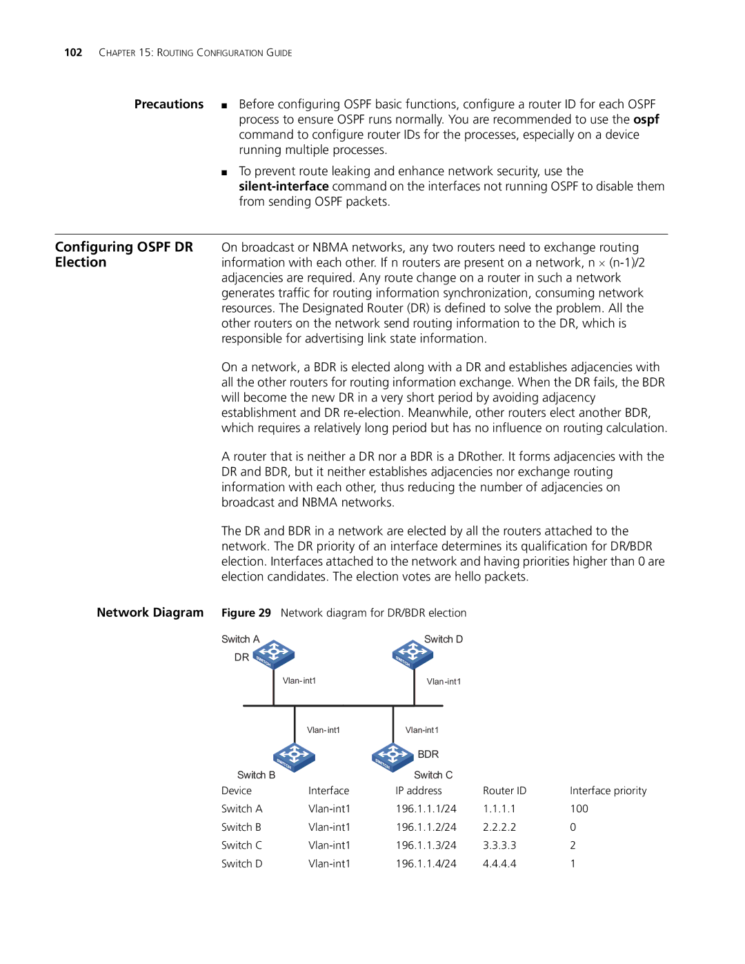
Network Diagram Figure 29
Switch A
DR ![]()
Network diagram for DR/BDR election
Switch D
|
|
|
|
|
|
| ||
|
|
| BDR |
|
| |
|
|
|
|
| ||
Switch B |
| Switch C |
|
| ||
Device | Interface | IP address | Router ID | Interface priority | ||
Switch A | 196.1.1.1/24 | 1.1.1.1 | 100 | |||
Switch B | 196.1.1.2/24 | 2.2.2.2 | 0 | |||
Switch C | 196.1.1.3/24 | 3.3.3.3 | 2 | |||
Switch D | 196.1.1.4/24 | 4.4.4.4 | 1 | |||