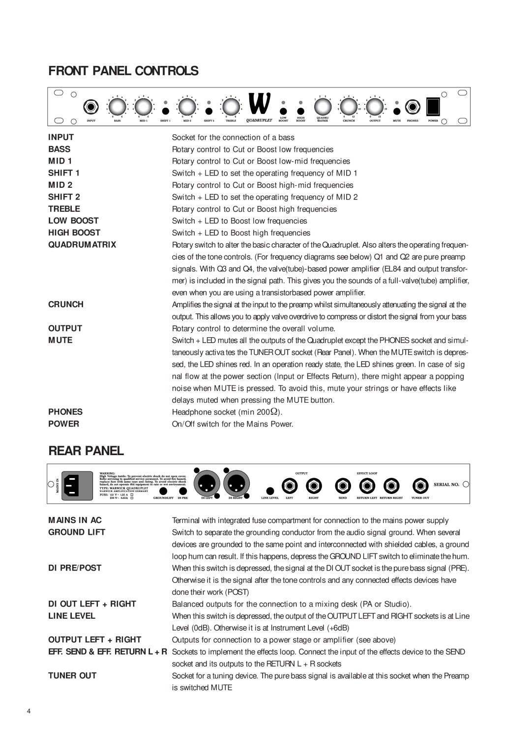
FRONT PANEL CONTROLS
INPUT | Socket for the connection of a bass |
BASS | Rotary control to Cut or Boost low frequencies |
MID 1 | Rotary control to Cut or Boost |
SHIFT 1 | Switch + LED to set the operating frequency of MID 1 |
MID 2 | Rotary control to Cut or Boost |
SHIFT 2 | Switch + LED to set the operating frequency of MID 2 |
TREBLE | Rotary control to Cut or Boost high frequencies |
LOW BOOST | Switch + LED to Boost low frequencies |
HIGH BOOST | Switch + LED to Boost high frequencies |
QUADRUMATRIX | Rotary switch to alter the basic character of the Quadruplet. Also alters the operating frequen- |
| cies of the tone controls. (For frequency diagrams see below) Q1 and Q2 are pure preamp |
| signals. With Q3 and Q4, the |
| mer) is included in the signal path. This gives you the sounds of a |
| even when you are using a transistorbased power amplifier. |
CRUNCH | Amplifies the signal at the input to the preamp whilst simultaneously attenuating the signal at the |
| output. This allows you to apply valve overdrive to compress or distort the signal from your bass |
OUTPUT | Rotary control to determine the overall volume. |
MUTE | Switch + LED mutes all the outputs of the Quadruplet except the PHONES socket and simul- |
| taneously activa tes the TUNER OUT socket (Rear Panel). When the MUTE switch is depres- |
| sed, the LED shines red. In an operation ready state, the LED shines green. In case of sig |
| nal flow at the power section (Input or Effects Return), there might appear a popping |
| noise when MUTE is pressed. To avoid this, mute your strings or have effects like |
| delays muted when pressing the MUTE button. |
PHONES | Headphone socket (min 200Ω). |
POWER | On/Off switch for the Mains Power. |
REAR PANEL
MAINS IN AC | Terminal with integrated fuse compartment for connection to the mains power supply |
GROUND LIFT | Switch to separate the grounding conductor from the audio signal ground. When several |
| devices are grounded to the same point and interconnected with shielded cables, a ground |
| loop hum can result. If this happens, depress the GROUND LIFT switch to eliminate the hum. |
DI PRE/POST | When this switch is depressed, the signal at the DI OUT socket is the pure bass signal (PRE). |
| Otherwise it is the signal after the tone controls and any connected effects devices have |
| done their work (POST) |
DI OUT LEFT + RIGHT | Balanced outputs for the connection to a mixing desk (PA or Studio). |
LINE LEVEL | When this switch is depressed, the output of the OUTPUT LEFT and RIGHT sockets is at Line |
| Level (0dB). Otherwise it is at Instrument Level (+6dB) |
OUTPUT LEFT + RIGHT | Outputs for connection to a power stage or amplifier (see above) |
EFF. SEND & EFF. RETURN L + R Sockets to implement the effects loop. Connect the input of the effects device to the SEND
| socket and its outputs to the RETURN L + R sockets |
TUNER OUT | Socket for a tuning device. The pure bass signal is available at this socket when the Preamp |
| is switched MUTE |
4