ESP25
Installation
(Continued)
Be careful not to strip or cross thread plastic fittings or check valves. Flex hose is not recommended. Rigid PVC or metal pipe is required for a permanent installation.
5.Place the pump with the 4’ section of PVC pipe on a solid, level surface in the sump pit on an elevated surface.
6.Attach a rubber check valve (sold separately) to the top of the discharge pipe. This will allow the pump or check valve to be removed easily for servicing.
NOTE: Check valves can be placed directly in the pump discharge if desired. However, for ease of disassembly, it is recommended that check valves be placed above the sump as shown in Figure 1.
The remainder of the discharge pipe installation will vary depending on individual circumstances. Using sound plumbing practices, route the
2.This pump has a 11/2” NPT discharge. If a 11/4” discharge pipe is desired, an adapter (not included) will be necessary. Smaller diameter piping will reduce pump flow, rate and performance.
3.A check valve will be required in the discharge line of BOTH the Main AC pump and the ESP25 pump to prevent recirculation of water into the sump pit. System will not function without two check valves.
4.Cut a 4’ section of 11/4" or 11/2" diameter rigid PVC pipe. Cement 11/2" pipe to a threaded fitting. Cement 11/4" pipe into pipe coupling. Attach 11/4" pipe section to the ESP25 discharge adapter.
5.Screw on to pump discharge.
Be careful not to strip or cross thread plastic fittings or check valves. Flex hose is not recommended. Rigid PVC or metal pipe is required for a permanent installation.
6.Place the pump with the 4’ section of PVC pipe on the sump floor or on an elevated surface if required.
7.Attach a rubber check valve (sold separately) to the top of the discharge pipe. This will allow the pump or check valve to be removed easily for servicing.
8.Duplicate the discharge piping arrangement for the primary AC pump if the existing discharge line has to be adjusted to accommodate a second pump.
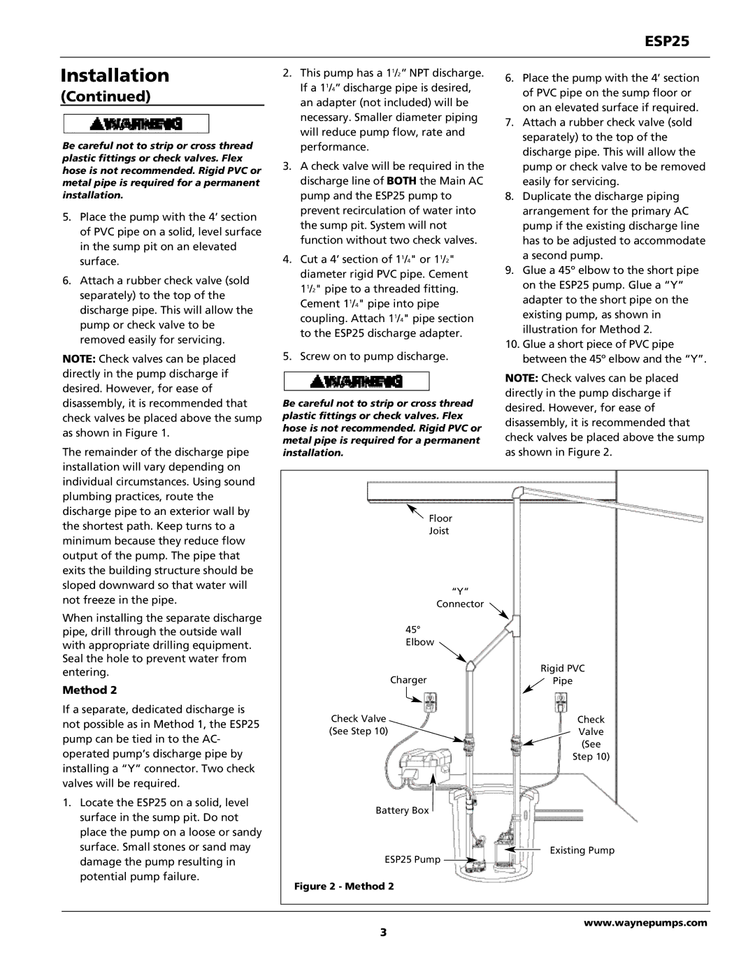
9.Glue a 45º elbow to the short pipe on the ESP25 pump. Glue a “Y” adapter to the short pipe on the existing pump, as shown in illustration for Method 2.
10.Glue a short piece of PVC pipe between the 45º elbow and the “Y”.
NOTE: Check valves can be placed directly in the pump discharge if desired. However, for ease of disassembly, it is recommended that check valves be placed above the sump as shown in Figure 2.
discharge pipe to an exterior wall by the shortest path. Keep turns to a minimum because they reduce flow output of the pump. The pipe that exits the building structure should be sloped downward so that water will not freeze in the pipe.
When installing the separate discharge pipe, drill through the outside wall with appropriate drilling equipment. Seal the hole to prevent water from entering.
Method 2
If a separate, dedicated discharge is not possible as in Method 1, the ESP25 pump can be tied in to the AC- operated pump’s discharge pipe by installing a “Y” connector. Two check valves will be required.
1.Locate the ESP25 on a solid, level surface in the sump pit. Do not place the pump on a loose or sandy surface. Small stones or sand may damage the pump resulting in potential pump failure.
![]() Floor
Floor
Joist
|
| “Y” |
|
| Connector |
45° |
| |
Elbow |
| |
Charger | Rigid PVC | |
Pipe | ||
|
|
|
Check Valve | Check | |
(See Step 10) | Valve | |
|
| (See |
|
| Step 10) |
Battery Box
Existing Pump
ESP25 Pump![]()
Figure 2 - Method 2
www.waynepumps.com
3