3/8”-16

3/8”-16 x 3/4”

Flag angle

Horizontal

Hex nut

Hex head bolt


track


Horizontal


track angle


Flag angle


(2) 1/4”-20 x 5/8”


(2) 1/4”-20

Carriage bolts


Flange hex nuts


Horizontal


track

15

Adjusting Top Fixtures

Tools: 7/16” Wrench, Step ladder


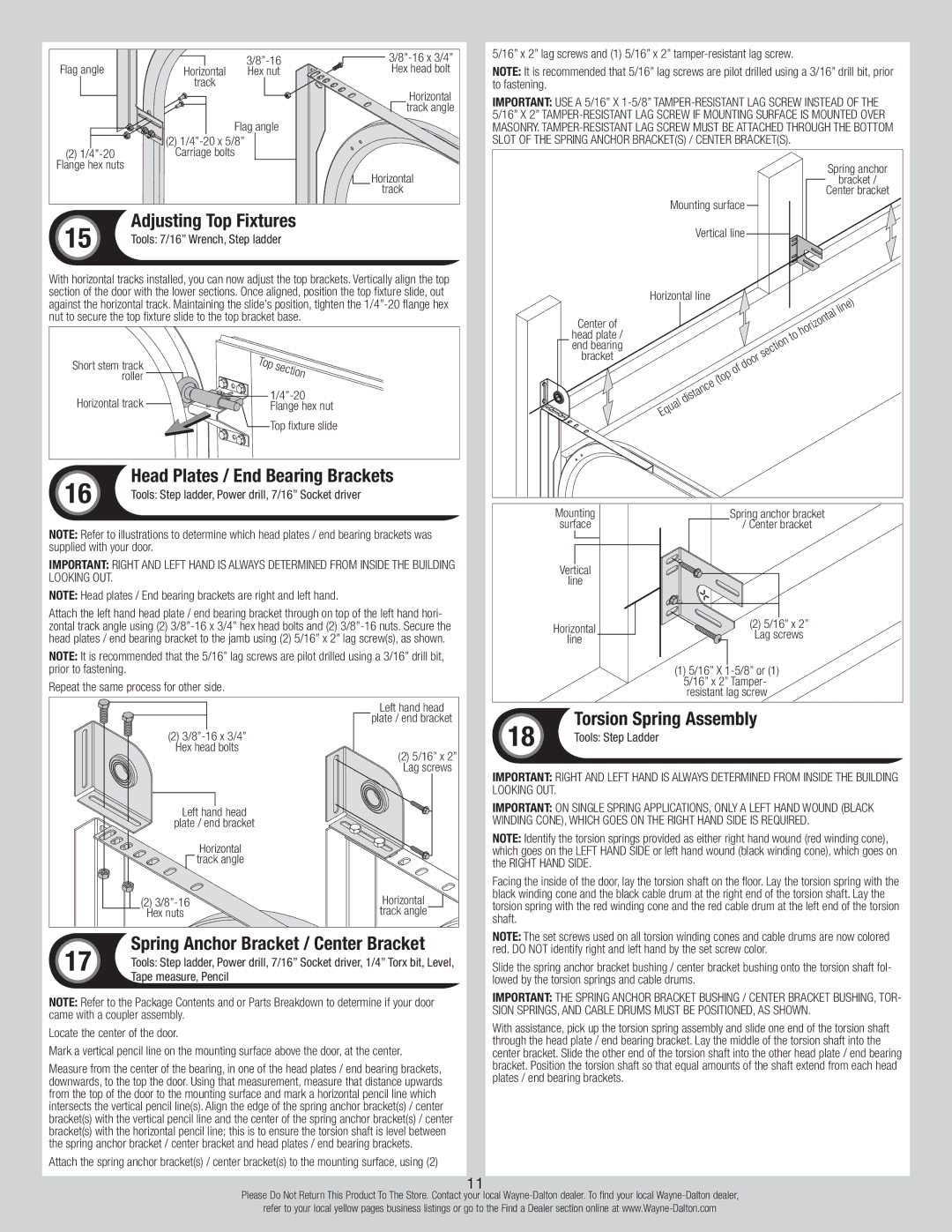
With horizontal tracks installed, you can now adjust the top brackets. Vertically align the top section of the door with the lower sections. Once aligned, position the top fixture slide, out against the horizontal track. Maintaining the slide’s position, tighten the 1/4”-20 flange hex nut to secure the top fixture slide to the top bracket base.

Short stem track

Top

section

roller


Horizontal track

1/4”-20

Flange hex nut

Top fixture slide

16

Head Plates / End Bearing Brackets

Tools: Step ladder, Power drill, 7/16” Socket driver


NOTE: Refer to illustrations to determine which head plates / end bearing brackets was supplied with your door.

IMPORTANT: Right and left hand is always determined from inside the building looking out.

NOTE: Head plates / End bearing brackets are right and left hand.

Attach the left hand head plate / end bearing bracket through on top of the left hand hori- zontal track angle using (2) 3/8”-16 x 3/4” hex head bolts and (2) 3/8”-16 nuts. Secure the head plates / end bearing bracket to the jamb using (2) 5/16” x 2” lag screw(s), as shown.

Note: It is recommended that the 5/16” lag screws are pilot drilled using a 3/16” drill bit, prior to fastening.

Repeat the same process for other side.


Left hand head


plate / end bracket

(2) 3/8”-16 x 3/4”


Hex head bolts

(2) 5/16” x 2”


Lag screws

Left hand head


plate / end bracket


Horizontal


track angle


(2) 3/8”-16

Horizontal

Hex nuts

track angle

17

Spring Anchor Bracket / Center Bracket

Tools: Step ladder, Power drill, 7/16” Socket driver, 1/4” Torx bit, Level,


Tape measure, Pencil

NOTE: Refer to the Package Contents and or Parts Breakdown to determine if your door came with a coupler assembly.

Locate the center of the door.

Mark a vertical pencil line on the mounting surface above the door, at the center.

Measure from the center of the bearing, in one of the head plates / end bearing brackets, downwards, to the top the door. Using that measurement, measure that distance upwards from the top of the door to the mounting surface and mark a horizontal pencil line which intersects the vertical pencil line(s). Align the edge of the spring anchor bracket(s) / center bracket(s) with the vertical pencil line and the center of the spring anchor bracket(s) / center bracket(s) with the horizontal pencil line; this is to ensure the torsion shaft is level between the spring anchor bracket / center bracket and head plates / end bearing brackets.

Attach the spring anchor bracket(s) / center bracket(s) to the mounting surface, using (2)

5/16” x 2” lag screws and (1) 5/16” x 2” tamper-resistant lag screw.

Note: It is recommended that 5/16” lag screws are pilot drilled using a 3/16” drill bit, prior to fastening.

IMPORTANT: Use a 5/16” x 1-5/8” tamper-resistant lag screw instead of the 5/16” x 2” tamper-resistant lag screw if mounting surface is mounted over masonry. Tamper-resistant lag screw must be attached through the bottom slot of the spring anchor bracket(s) / center bracket(s).


Spring anchor


bracket /


Center bracket


Mounting surface


Vertical line


Horizontal line


line)

Center of

horizontal

head plate /

to

end bearing

section

bracket


door


of


(top


distance


Equal

Mounting

Spring anchor bracket

surface

/ Center bracket

Vertical


line


Horizontal

(2) 5/16” x 2”

Lag screws

line


(1) 5/16” X 1-5/8” or (1)


5/16” x 2” Tamper-


resistant lag screw

18

Torsion Spring Assembly

Tools: Step Ladder


IMPORTANT: Right and left hand is always determined from inside the building looking out.

IMPORTANT: On single spring applications, only a left hand wound (black winding cone), which goes on the RIGHT HAND SIDE is required.

NOTE: Identify the torsion springs provided as either right hand wound (red winding cone), which goes on the LEFT HAND SIDE or left hand wound (black winding cone), which goes on the RIGHT HAND SIDE.

Facing the inside of the door, lay the torsion shaft on the floor. Lay the torsion spring with the black winding cone and the black cable drum at the right end of the torsion shaft. Lay the torsion spring with the red winding cone and the red cable drum at the left end of the torsion shaft.

NOTE: The set screws used on all torsion winding cones and cable drums are now colored red. DO NOT identify right and left hand by the set screw color.

Slide the spring anchor bracket bushing / center bracket bushing onto the torsion shaft fol- lowed by the torsion springs and cable drums.

IMPORTANT: The spring anchor bracket bushing / center bracket bushing, tor- sion springs, and cable drums must be positioned, as shown.

With assistance, pick up the torsion spring assembly and slide one end of the torsion shaft through the head plate / end bearing bracket. Lay the middle of the torsion shaft into the center bracket. Slide the other end of the torsion shaft into the other head plate / end bearing bracket. Position the torsion shaft so that equal amounts of the shaft extend from each head plates / end bearing brackets.

11

Please Do Not Return This Product To The Store. Contact your local Wayne-Dalton dealer. To find your local Wayne-Dalton dealer,

refer to your local yellow pages business listings or go to the Find a Dealer section online at www.Wayne-Dalton.com

Page 11
Image 11
Wayne-Dalton 8300/8500 Spring Anchor Bracket / Center Bracket, Adjusting Top Fixtures, Head Plates / End Bearing Brackets

8300/8500 specifications

Wayne-Dalton has established itself as a leader in the garage door industry, and their Model 8300/8500 series exemplifies their commitment to quality and innovation. These models are designed for residential homeowners seeking a combination of security, energy efficiency, and aesthetic appeal.

The Wayne-Dalton 8300 model is crafted with a steel construction that prioritizes durability and low maintenance. It features a unique embossed design that mimics the look of real wood, allowing homeowners to achieve a classic appearance without the upkeep. The garage doors come with a variety of color options, enabling customers to select a finish that harmonizes with their home’s exterior.

The 8500 model, on the other hand, introduces superior insulation properties. Constructed with two layers of galvanized steel and a core filled with polystyrene insulation, the 8500 ensures better energy efficiency. This feature is particularly beneficial for homeowners in regions with extreme temperatures, as it helps maintain a consistent indoor environment while reducing energy costs.

Both the 8300 and 8500 models prioritize security features. Wayne-Dalton incorporates a unique locking mechanism and optional security codes to deter unauthorized access. Additionally, the lightweight design aids in smooth operation, reducing wear and tear on the garage door opener.

Technology is another focal point for the Wayne-Dalton line. Both models are compatible with the latest smart home technology, enabling seamless operation via mobile apps. Homeowners can receive notifications, monitor the garage door’s status, and control it remotely, enhancing convenience and peace of mind.

Another notable characteristic is the quiet operation of both models, thanks to their well-engineered torsion spring system. This feature minimizes noise during opening and closing, making them an ideal choice for attached garages where sound can disrupt daily life.

Wayne-Dalton also offers a variety of window options for the 8300/8500 series, allowing homeowners to customize their doors further, adding natural light while maintaining privacy. The options include decorative glass and traditional window placements.

In summary, the Wayne-Dalton 8300/8500 garage doors deliver a perfect blend of aesthetics, durability, and energy efficiency. With advanced technologies, reinforcing security, and exceptional insulation properties, these models cater to the modern homeowner's needs, solidifying Wayne-Dalton’s reputation for excellence in the garage door market.