| (3) | 1/4”- 20 x 7/8” |
| ||
| (4) | 5/16”- 18 x 3/4” |
Upper half | Bolts and nuts | |
|
| |
|
| |
Lower half | (4) | 1/4”- 20 x 5/8” |
| ||
| ||
12 | Attaching Hor Tracks to Vertical Tracks | |
Tools: Ratchet wrench, 7/16” Socket, 9/16” Socket, 9/16” Wrench, | ||
| ||
| level, Step ladder |
Note: If you have F.A. flag angles, complete this step.
To install horizontal track, place the curved end over the top roller of the top section. Align the bottom of the horizontal track with the top of the vertical track. Tighten the horizontal track to the flag angle with (2)
![]() WARNING
WARNING
Do not raise door until horizontal tracks are secured at rear, as outlined in step, Rear Support, or door could fall from over- head position causing severe or fatal injury.
Level the horizontal track assembly and bolt the horizontal angle to the first encountered slot in the flag angle using (1)
Remove the nail that was temporarily holding the top section in place, installed in step, Top Section.
Important: Failure to remove nail before attempting to raise door could cause permanent damage to top section.
Note: If an idrive® opener will be installed, position horizontal tracks slightly above level.
Horizontal | ||
track | Hex nut | |
Horizontal | ||
Flange hex nuts | ||
angle | ||
| ||
Flag angle |
| |
Track bolts | Truss head bolt |
13 | Adjusting Top Brackets | |
Tools: 7/16” Wrench, Step ladder | ||
|
With horizontal tracks installed, you can now adjust the top brackets. Vertically align the top section of the door with the lower sections. Once aligned, position the top bracket slide out against the horizontal track. Maintaining the slide’s position, tighten the
|
|
|
|
| section | |
|
|
|
|
| Top | |
Horizontal track |
|
|
| Top bracket slide | ||
|
|
|
|
| ||
|
|
|
|
| ||
|
|
|
|
| ||
Roller |
|
|
|
| Hex nut | |
|
|
| ||||
|
|
|
|
|
|
|
14 | End Bearing Brackets | |
Tools: Step ladder, Power drill, Ratchet wrench, 7/16” Socket driver, | ||
| ||
| 9/16” Socket, 9/16” Wrench |
IMPORTANT: Right and left hand is always determined from inside the building looking out.
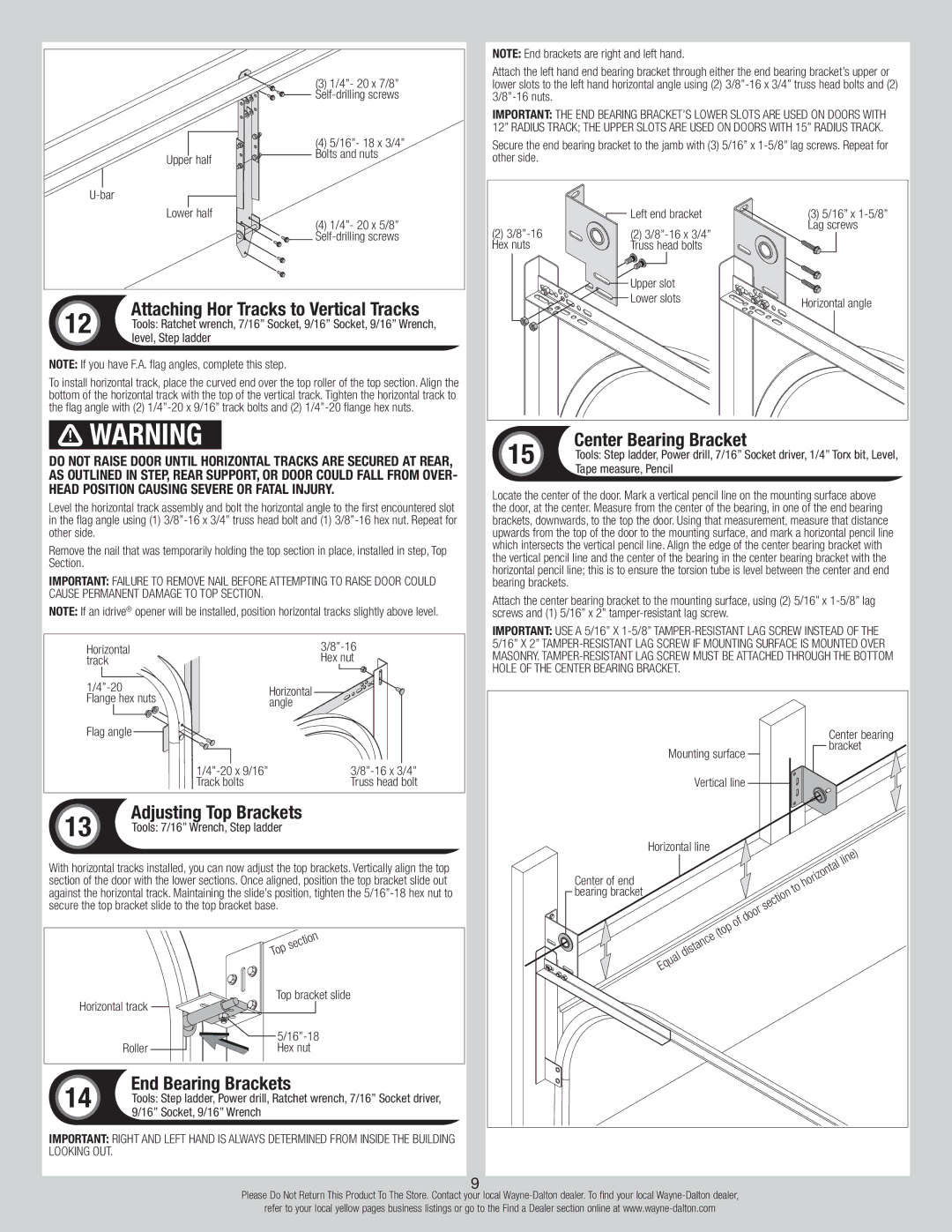
NOTE: End brackets are right and left hand.
Attach the left hand end bearing bracket through either the end bearing bracket’s upper or lower slots to the left hand horizontal angle using (2)
IMPORTANT: The end bearing bracket’s lower slots are used on doors with 12” radius track; the upper slots are used on doors with 15” radius track.
Secure the end bearing bracket to the jamb with (3) 5/16” x
| Left end bracket | (3) 5/16” x |
(2) | (2) | Lag screws |
| ||
Hex nuts | Truss head bolts |
|
| Upper slot |
|
| Lower slots | Horizontal angle |
|
|
15 | Center Bearing Bracket | |
Tools: Step ladder, Power drill, 7/16” Socket driver, 1/4” Torx bit, Level, | ||
| ||
| Tape measure, Pencil |
Locate the center of the door. Mark a vertical pencil line on the mounting surface above the door, at the center. Measure from the center of the bearing, in one of the end bearing brackets, downwards, to the top the door. Using that measurement, measure that distance upwards from the top of the door to the mounting surface, and mark a horizontal pencil line which intersects the vertical pencil line. Align the edge of the center bearing bracket with the vertical pencil line and the center of the bearing in the center bearing bracket with the horizontal pencil line; this is to ensure the torsion tube is level between the center and end bearing brackets.
Attach the center bearing bracket to the mounting surface, using (2) 5/16” x
IMPORTANT: Use a 5/16” x
|
| Center bearing |
| Mounting surface | bracket |
|
| |
| Vertical line |
|
| Horizontal line |
|
|
| line) |
Center of end |
| horizontal |
|
| |
bearing bracket |
| to |
| section | |
|
| |
| door | |
| of |
|
| (top |
|
| distance |
|
| Equal |
|
9
Please Do Not Return This Product To The Store. Contact your local
refer to your local yellow pages business listings or go to the Find a Dealer section online at