...CONTINUED INSTALLATION INSTRUCTIONS | | | | | | | | | | | | | |
19 | WARNING! | 12A | | ALTERNATE INSTALLATIONS | | 12A | | 5500/9700 ESTATE™ |
Prior to winding or making adjustments to the springs, ensure you’re winding in the | | | |
proper direction as stated in the Installation Instructions. Otherwise the spring fit- | If you are not installing the idrive™ operator on your garage door, you must install the center bracket bushing assembly. Follow these instructions for a non-idrive™ operated garage doors. TorqueMaster™ | | |
tings may release from spring if not wound in the proper direction and could result | springs come lubricated and pre-assembled inside the torque tube. To install, lay the torque tube on the floor in front of the door with the labeled end to the left. Slide the center bracket/bushing assembly onto the | | | LIFETIME LIMITED WARRANTY |
in severe or fatal injury. | torque tube, from the right hand side, toward the center. Shake the TorqueMaster™ tube gently to extend the winding shafts out about 5” on both ends. Single spring TorqueMaster will only have the right hand | | | | |
IMPORTANT! DO NOT USE IMPACT GUN TO WIND SPRING(S) | spring. Slide center bracket bushing assembly from the right side to the center of the torque tube. | | | 12B | | | | Wayne-Dalton Corp. | |
Beginning with the right hand side. Press and hold in the canoe clip. Ensure the cable is in the first groove of the drum. | IMPORTANT! Right and left hand is always determined from inside the building looking out. | | | | | | P.O. Box 67, Mt. Hope, Ohio 44660 | |
Using an electric drill (high torque gear reduced to 1300 RPM preferred) with a 7/16” socket, carefully rotate right hand | | | | | | | | | | | www.wayne-dalton.com | |
12B | | | | | | | | | | Subject to the terms and conditions contained in this Lifetime Limited Warranty, Wayne-Dalton Corp. (“Manufacturer”) warrants the |
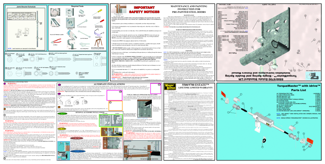
winding bolt clockwise, until counter shows 2-3 turns. This will keep the counterbalance cable taut while adjusting the | | | | | | | TYPICAL TROLLEY OPERATOR INSTALLATION | sections of the door, which is described at the top of this page, for as long as you own the door against: |
When installing a DoorMaster™ operator replace the bushing with the drive gear (located in DoorMaster™ | | | (i) | Peeling, cracking, or chalking of the original factory-applied coating on the door as a result of a defect in the original |
left hand side counterbalance cable. Repeat step 18 and 19 for left side. | | | If you are installing an electric operator on your door, the following information is pro- | factory-applied coating or in the application of the original factory-applied coating, in cases where the door sections and the original |
NOTE: Single spring applications require no spring winding on the left hand side. | package). | | | | | | |
| | | | | | vided to ensure proper function of your door/operator installation. Figure below shows | factory-applied coating: (a) have not been subjected to adverse atmospheric conditions or contaminates (such as salt water or |
Ensure counterbalance cable tension is equal for both sides prior to fully winding spring(s) to appropriately 15 1/2 turns | | | | | | | | other marine environment, or to toxic or abrasive substances, including those in the air); (b) have been maintained in compliance |
| | | | | | | a typical means of connecting the operator arm to the operator stile located in the center |
for solid sections, or 15 turns for glazed top sections. Carefully rotate the winding bolt head clockwise until the counter | | | | | | | | with Manufacturer’s recommendations; and | (c) have not been subject to physical abrasion, impacted by a hard object, or have been |
| | | | | | | of the top section. | | |
shows the correct number of turns for your door. Repeat for the opposite side on double spring TorqueMaster™ systems. | | | | | | | | | | punctured. | | |
| | | | | | | | | | (ii) | The door becoming inoperable due to rust-through of the steel skin from the core of the door section, caused by cracking, |
If door raises off the floor remove 1/2 - 1 full turn from each spring before proceeding. After spring is wound, hold the | | | | | | 16 | | | | |
| | | | | | | | | splitting, or other deterioration of the steel skin, or due to structural failure caused by separation or degradation of the foam insulation. |
lock nut (in back of end bracket) stationary with a 7/16” wrench while rotating the winding bolt clockwise until snug. | | | | | | | | | |
| | | | | | | | | | The Manufacturer warrants the garage door hardware (except springs) and the tracks of the above-described door, for as long as you |
Tightening of the lock nut prevents spring from unwinding. Repeat for opposite side if necessary. | | | | | | | | | | | own the door, against defects in material and workmanship, subject to all the terms and conditions below. |
IMPORTANT! Adjustments to the recommended number of turns may be required. | | | | | | | | | | | The Manufacturer warrants those component parts of the door not covered by the preceding provisions of this Lifetime Limited |
AFTER REAR SUPPORTASSEMBLY IS COMPLETE, check door balance. If door raises off the floor under spring tension | 16 | | | | | | | | | | Warranty against defects in material and workmanship for a period of ONE (1) YEAR from the date of installation. |
alone, then reduce turns until door will rest on floor. A “hot” door such as this can cause idrive™ operation problems. | | | | | | | | | TYPICAL OP- | The Manufacturer warrants the factory-applied finish and the factory attached stiles against fading and cosmetic changes from the time |
| | | | | | | | | of installation for TWO (2) YEARS. The factory attached stiles are warranted against peeling, cracking, chalking, or delamination from the time of |
20 | | To locate the center bracket, mark the header halfway between the flagangles and level the TorqueMaster tube. Fas- | | | | | ERATOR ARM |
| | | | | installation for TWO (2) YEARS. If the door is re-stained or re-painted, the TWO (2) YEARS warranty for the factory-applied finish is void. |
Drum wraps are identified as right and left. To install, place the drum wrap over the cable drum and under the idrive™ | ten the metal bracket to the header using (2) 1/4” x 1-1/2” lag screws. | | | | | | | (SUPPLIED WITH | After a period of TWENTY (20) YEARS, from time of installation, replacement of Lifetime Limited Warranty materials will be pro- |
| | | | | | | | | OPERATOR) | rated at 50 per cent of Manufacturer’s published list pricing at time of claim, and you must pay this amount. |
disconnect cable (if installed). Align the outside flange over the outside edge of the cable drum and push the drum wrap | | | OPTIONAL ACCESSORY INSTALLATIONS | | | | |
| | | | | | | is installed) as his/her primary residence (“Buyer”). This Limited Warranty does not apply to residences other than primary, or to commercial or |
down onto the cable drum. | | | | | | | |
| | | | | | | | | | | | This Limited Warranty is extended only to the person who purchased the product and continues to own the premises (where the door |
21 | | STEP PLATES | | | (OUTSIDE) | | (INSIDE) | SEE OPERATOR BRACKET | | | industrial installations, or to installations on rental property (even when used by a tenant as a residence). This Limited Warranty is not transferable |
| | | | | | | | | |
| Raise the door to a comfortable working height and secure with locking pliers to the track. Locate the | DRILL THROUGH | | | INSTRUCTIONS FOR DE- | | | to any other person (even when the premises is sold), nor does it extend benefits to any other person. As a result this Limited Warranty does NOT |
Hold the door down to prevent it from rising unexpectedly in the event the spring(s) was overwound and carefully re- | center stile on the bottom section of the door. Using the pre-punched holes at the bottom of the stile as | SECTION WITH A 7/16” | | TAILS ON INSTALLATION | | | apply to any person who purchases the product from someone other than an authorized Wayne-Dalton dealer or distributor. |
move the locking pliers from the vertical tracks. Raise the door until the top section and half of the next section are in a | a template, drill (2) 7/32” (6mm) dia. holes through the section. Using the previously drilled holes as a | (11mm) DIA. DRILL BIT | | | Installation Tips: | | The Manufacturer will not be responsible for any damage attributable to improper storage, improper installation, or any alteration |
| | | of the door or its components, abuse, damage from corrosive fumes or substances, salt spray or saltwater air, fire, Acts of God, failure to properly |
horizontal position. Do not raise door any further since rear of horizontal track is not yet supported. | guide, enlarge the holes from outside the door to 7/16” (11mm) dia. and assemble the outside and inside | | | | | | |
| | | (2) | 1. Follow the installation instructions supplied with your operator. | | maintain the door, or attempt to use the door, its components or related products for other than its intended purpose and its customary usage. This |
WARNING! | step plates to the section using (2) #8 x 1-5/8” screws. | | | | | Limited Warranty does not cover ordinary wear. This Limited Warranty will be voided if the original finish is painted over, unless Manufacturer’s |
| | | #8 x 1-5/8” | 2. Reinforce top section prior to attaching operator. | |
NOTE: Do not drill through or enlarge holes on the inside of the door. | | | | | preparation and painting instructions are followed explicitly. This Limited Warranty will be voided if any holes are drilled into the door, other than |
RAISING DOOR FURTHER CAN RESULT IN DOOR FALLING AND CAUSING SEVERE OR FATAL INJURY. | WARNING! To avoid serious injury to fingers or hands, | | | | SCREWS | 3. Install trolley rail 1/2” to 1” (13 - 25 mm) above high arc of top section of the door. | those specified by the Manufacturer. | |
| | | | |
Now clamp a pair of locking pliers to the vertical tracks just above the second roller on one side, and just below the second | | | | | 4. Mount operator to ceiling so that 1” to 1-1/2” (25 - 38 mm) clearance is maintained | THIS LIMITED WARRANTY COVERS A CONSUMER PRODUCT AS DEFINED BY THE MAGNUSON-MOSS ACT. NO |
| | | | | | | | | | | |
roller on the other side. This will prevent the door from raising or lowering while installing the rear support. Using | never place fingers or hands between door sections and track | | | | | between trolley rail and top section when door is fully open (trolley rail will slope | WARRANTIES, EXPRESS OR IMPLIED (INCLUDING BUT NOT LIMITED TO THE WARRANTY OF MERCHANTABILITY OR FITNESS |
| | | | FOR A PARTICULAR PURPOSE) WILL EXTEND BEYOND THE TIME PERIOD SET FORTH IN UNDERSCORED BOLD FACE TYPE IN |
perforated angle, 2” lag screws and 5/16” bolts with nuts (may not be supplied), fabricate rear support for horizontal | when operating door. Always use step plate when manually oper- | | | | | down towards rear). | | | THIS LIMITED WARRANTY, ABOVE. | |
tracks. Attach horizontal tracks to the rear supports with 5/16”-18 x 1-1/4” hex bolts and nuts (may not be supplied). | ating door. | | | | No.6 | | 5. The operator bracket must be mounted to the operator muntin on the top section. | • | Some States do not allow limitations on how long an implied warranty lasts, so the above limitations may |
Horizontal tracks must be level and parallel with door. | PULL ROPE | | | | | 6. Attach operator rail securely to spring pad. | | | not apply to you. | |
| | | | | Any claim under this Limited Warranty must be made in writing, within the applicable warranty period, to the dealer from which the |
WARNING! | Attach No. 6 screw eye to wood jamb approximately 48” - 50” (1220 - 1270 mm) off the floor. Use (1) 1/4”-14 | screw | | 7. Attach operator to ceiling using perforated angle. | |
eye | | | made at all. | | |
| 8. IMPORTANT! ANGLE MUST BE ATTACHED TO FRAMING MEMBER(S) | | |
| | | | | | | | product was purchased. Unless the dealer is no longer in business, a written claim to the Manufacturer will be the same as if no claim had been |
KEEP HORIZONTAL TRACK PARALLEL AND WITHIN 3/4” OF DOOR EDGE, OTHERWISE DOOR COULD | x 5/8” selftapping screw to fasten pull rope clip to the end stile and then tie the pull rope to both the screw eye | | | | WARNING! OPERATOR MUST BE TESTED AT TIME OF INSTAL- | At the Manufacturer’s option, pursuant to the dealer having notified the Manufacturer of a warranty claim, a service representative |
and the pull rope clip. | | | | | |
FALL, RESULTING IN SEVERE OR FATAL INJURY. | | | | | | may inspect the product on site, or Buyer may be required to return the product to the Manufacturer at Buyer’s expense. Buyer agrees to cooperate |
Permanently attach the vinyl weather stripping to both door jambs and the header, Fig. 5C. Now, lift the door and check | WARNING! DO NOT INSTALL PULL ROPE ON DOORS WITH ELECTRIC OP- | | rope | LATION AND MONTHLY THERE AFTER, ACCORDING TO THE MANUFAC- | with any representative of the Manufacturer and to give such representative full access to the product with the claimed defect and full access to the |
| TURER’S INSTRUCTIONS TO ENSURE THAT ALL SAFETY FEATURES ARE | location of its installation. | |
it’s balance. Adjust, if door lifts by itself (also hard to pull down) or if door is difficult to lift (too easy to pull down). | ERATORS. CHILDREN MAY BECOME ENTANGLED IN THE ROPE RESULTING SEVERE | | | | If the Manufacturer determines that the claim is valid under the terms of this Limited Warranty, the Manufacturer will cause the |
Anytime spring adjustments are made you must loosen the lock nuts to begin with and retighten both lock nuts afterwards. | OR FATAL INJURY. | INSIDE SIDE LOCK | | TRACK | END STILE | (4) 1/4”-20x11/16” | FUNCTIONING CORRECTLY. FAILURE TO PERFORM THESE TESTS AND | defective product to be repaired or replaced. The decision about the manner in which the defect will be remedied will be at the discretion of the |
To adjust spring(s), only add or remove 1/4 turn on the counter reading at a time. Adjust both sides equally. | | | | (2) 1/4”-20x9/16” | | SELF DRILLING | MAKE ANY NECESSARY ADJUSTMENTS/REPAIRS CAN RESULT IN SEVERE | Manufacturer, subject to applicable law. THE REMEDY WILL COVER ONLY MATERIAL. THIS LIMITED WARRANTY DOES NOT COVER |
IMPORTANT! Do not add or remove more than 1 spring turn from specified amount. | | | Select desired side of door for lock placement. Locate the striker plates over the | TRACK BOLTS | | SCREWS | OR FATAL INJURY. | | | OTHER CHARGES, SUCH AS FIELD SERVICE LABOR FOR REMOVAL, INSTALLATION, PAINTING, SHIPPING, ETC. |
| | | | | | Any repairs or replacements arranged by Manufacturer will be covered by (and subject to) the terms, conditions, limitations and |
If the door still does not operate easily, lower the door into the closed position, UNWIND SPRING(S) TO ZERO, and | | | pre-punched holes in the vertical track on the selected side, nearest the center | | | | | | | exceptions of this Limited Warranty; provided, however, that the installation date for the repaired or replaced product will be deemed to be the |
recheck the following items: | f | 2” | of the lock(second) section. Fasten the stiker plate to the vertical track using (2) | | | | | 8 | | date the original product was installed, and this Limited Warranty will expire at the same time as if there had been no defect. If a claim under this |
1.) Check the door for level. | | STRUT | 1/4”-20 x 9/16” track bolts and flanged hex nuts. The side lock should be spaced | | | | | | | Limited Warranty is resolved in a manner other than described in the immediately preceding paragraph, then neither this Limited Warranty nor any |
| in approximately 1/8” from the edge of the section. Ensure that the lock is square | | | | | | | other warranty from the Manufacturer will cover the repaired or replaced portion of the product. |
2.) Check the TorqueMaster™ tube and flagangles for level and plumb. | | | | | | 6 | | |
| | with the section and the lock bolt aligns with the striker plate. Secure the lock to | | | | | | THE REMEDIES FOR THE BUYER DESCRIBED IN THIS LIMITED WARRANTY ARE EXCLUSIVE and take the place |
3.) Check the distance between the flagangles - must be door width plus 3-3/8” to 3-1/2”. | | | the end stile with (4) 1/4”-20x11/16” self-drilling screws. IMPORTANT! Side | STRIKER | | | 3 | | 7 | of any other remedy. The liability of the Manufacturer, whether in contract or tort, under warranty, product liability, or otherwise, will not go |
4.) Check the counterbalance cables for equal tension - loosen set screws and adjust if necessary. | | | SLIDE | SIDE LOCK | | 4 | beyond the Manufacturer’s obligation to repair or replace, at its option, as described above. THE MANUFACTURER WILL NOT UNDER ANY |
| | locks must be removed or made inoperative in the unlocked position if an | PLATE | | | CIRCUMSTANCES BE LIABLE FOR SPECIAL, INCIDENTAL, OR CONSEQUENTIAL DAMAGES, including (but not limited to) damage or |
5.) Rewind the spring(s). | | | operator is installed on the door. | | | | | | | |
| | | | | | | | | loss of other property or equipment, personal injury, loss of profits or revenues, business or service interruptions, cost of capital , cost of purchase or |
6.) Make sure door isn’t rubbing on jambs. | | | OPERATOR BRACKET | | | | | | | | replacement of other goods, or claims of third parties for any of the foregoing. |
NOTE: As a safety feature, the right hand end bracket on single spring applications, both right hand and left hand end | | f | | | | | | | | • | Some States do not allow the exclusion or limitation of incidental or consequential damages, so the above limitation or |
brackets double springs applications, cannot be disassembled for service until the spring(s) is completely unwound and | | Locate the center of the top section’s strut. The strut is factory attached with ¼” – 14 x 5/8” self tapping screws. Remove, but retain, a | | | | | exclusion may not apply to you. | |
f | | 5 | | | No employee, distributor, dealer, representative, or other person has the authority to modify any term or condition contained in this |
the counter cover reads zero. | | few of these screws (approximately 4-6 from the center of the strut, allowing the operator bracket to slide between the section and the | | | Limited Warranty or to grant any other warranty on behalf of or binding on the Manufacturer, and anyone’s attempt to do so will be null and void. |
After door installation is completed, refer to the idrive™ owner’s manual, starting at the PRE-OPERATION INSTAL- | | | strut. Slide the operator bracket until it seats on the male part of the section. The operator bracket must be centered and positioned on | | | | Buyer should be prepared to verify the date of installation to the satisfaction of the Manufacturer. |
LATION section to complete the opener installation. | | | the top section so it bridges the transition point of the section thickness. Attach the operator bracket using (8) ¼” – 14 x 5/8” self tapping | | | | The rights and obligations of the Manufacturer and Buyer under this Limited Warranty will be governed by the laws of the State of |
22 | | (STRUTS | | screws as shown. Re-attach the strut using (2) ¼” – 20 x 11/16” self drilling screws through the operator bracket. Finish re-attaching the | 2 | | | Ohio, USA, to the extent permitted by law. | |
| e | strut using the self tapping screws removed previously. | | | | | TOP SECTION MUST BE REINFORCED | • | This Limited Warranty gives you specific legal rights and you may also have other rights, which may vary from State to |
If there are stiles or lite frame dividers included with your door, install them per their instructions at this time. | ONLY) | | | | | | | State. | © Copyright 2009 Wayne-Dalton Corporation |
| | | | | | | | | | |