|
|
|
| Model EFL33 | |
General Safety Information |
| a 45º angle with the valve pivot on | 7. When a tether switch is used, rigid | ||
(Continued) |
| top. In a vertical position, solids will | discharge pipe is required. If the | ||
The pump motor |
| tend to lodge on the valve flapper | pump is allowed to move, the | ||
| and can prevent it from opening. | tether switch could be restricted | |||
is equipped with |
| ||||
|
|
| by the basin wall, preventing the | ||
automatic resetting thermal protector | 3. | Drill a 1/8 inch hole in the discharge | |||
and may restart unexpectedly. Protector |
| pipe approximately 1 inch to 2 inch | pump from operating. | ||
tripping is an indication of motor |
|
| |||
| above the pump discharge when | Before removing | |||
overloading as a result of operating |
| ||||
| a check valve is used. The hole | pump from basin | |||
the pump at low heads (low discharge |
| ||||
restriction), excessively high or low |
| prevents air locking of the pump at | for service, always disconnect electrical | ||
voltage, inadequate wiring, incorrect |
| the initial | power to pump and control switch. For | ||
motor conditions, or a defective motor |
| lose prime. |
| any work on pump or switch, always | |
or pump. |
|
| unplug the power cord. Do not just turn | ||
4. | A gate valve should be installed in | ||||
14. IThis pump is designed to transfer | off circuit breaker or unscrew fuse. | ||||
| the system after the check valve. This |
| |||
water in cycles. Using this pump in |
|
| |||
| gate valve should be a full port valve | Maintenance | |||
a continuous duty application by |
| ||||
| which will pass 3/4 inch solids or as | Make certain that | |||
manipulating the switch to stay on, |
| ||||
| required by state and local codes. | ||||
will affect the performance and the |
| the pump is | |||
| This gate valve permits removal of | unplugged before attempting to service | |||
life of the product. |
| ||||
| the pump and/or check valve for | or remove any component. This pump is | |||
15. Protect electrical cord from sharp |
| ||||
| servicing. |
| assembled in the factory using special | ||
objects, hot surfaces, oil, and | 5. A union should be installed between | equipment; therefore only authorized | |||
chemicals. Avoid kinking the cord. | service dealers or qualified electricians | ||||
| the check valve and the pump so the | ||||
Replace or repair damaged or worn |
| should attempt to repair this unit. | |||
| pump can be removed with least | ||||
cords immediately. Use wire of |
| Improper repair can cause an electrical | |||
| disturbance of the piping. |
| |||
adequate size to minimize voltage |
|
| shock hazard. | ||
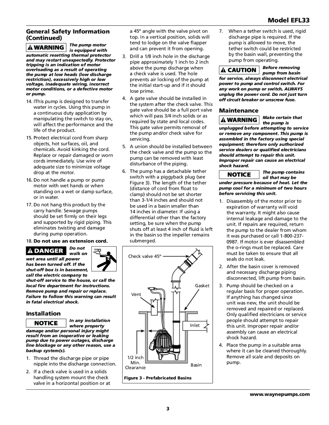
6. The pump has a detachable tether | |||||
drop at the motor. | The pump contains | ||||
16. Do not handle a pump or pump |
| switch with a piggyback plug (see | oil that may be | ||
| Figure 3). The length of the tether | under pressure because of heat. Let the | |||
motor with wet hands or when |
| ||||
| (distance of cord from float to | pump cool for a minimum of two hours | |||
standing on a wet or damp surface, |
| ||||
| clamp) should not be set shorter | before servicing this unit. | |||
or in water. |
| ||||
| than | 1. Disassembly of the motor prior to | |||
17. Do not hang this product by the |
| ||||
| be used in a basin smaller than | expiration of warranty will void | |||
carry handle. Sewage pumps |
| 14 inches in diameter. If using a | the warranty. It might also cause | ||
should be set firmly on their legs |
| differential other than the factory | internal leakage and damage to the | ||
and supported by rigid piping. This |
| setting, be sure when the pump | unit. If repairs are required, return | ||
eliminates twisting and damage |
| shuts off at least 4 inch of fluid is left | the pump to the dealer from whom | ||
during pump operation. |
| in the basin so the impeller remains | it was purchased or call | ||
18. Do not use an extension cord. |
| submerged. |
| 0987. If motor is ever disassembled | |
Do not |
|
|
| the | |
walk on |
| Check valve 45º |
| must be taken to ensure that all | |
wet area until all power |
|
| seals do not leak. | ||
|
|
| |||
has been turned off. If the |
|
|
| 2. After the basin cover is removed | |
|
|
| |||
|
|
| and necessary discharge piping | ||
call the electric company to |
|
|
| ||
|
|
| disconnected, lift pump from basin. | ||
|
|
| |||
|
|
| 3. Pump should be checked on a | ||
local fire department for instructions. |
|
| Gasket | ||
Remove pump and repair or replace. |
| Vent |
| regular basis for proper operation. | |
Failure to follow this warning can result |
|
| If anything has changed since | ||
|
|
| |||
in fatal electrical shock. |
|
|
| unit was new, the unit should be | |
Installation |
|
|
| removed and repaired or replaced. | |
|
|
| Only qualified electricians or service | ||
In any installation |
|
| Inlet | people should attempt to repair | |
where property |
|
| this unit. Improper repair and/or | ||
damage and/or personal injury might |
|
|
| assembly can cause an electrical | |
result from an inoperative or leaking |
|
|
| shock hazard. | |
pump due to power outages, discharge |
|
|
| ||
|
|
| 4. Place the pump in a suitable area | ||
line blockage or any other reason, use a |
|
|
| ||
backup system(s). |
|
|
| where it can be cleaned thoroughly. | |
1. Thread the discharge pipe or pipe |
| 1/2 inch |
| Remove all scale and deposits on | |
nipple into the discharge connection. |
| Min. | Basin | pump. | |
Clearance |
| ||||
2. If a check valve is used in a solids |
|
| |||
|
|
|
| ||
handling system mount the check | Figure 3 - Prefabricated Basins |
| |||
valve in a horizontal position or at |
|
|
|
| |
|
|
|
| www.waynepumps.com | |
|
| 3 |
|
| |