Manual de instrucciones de funcionamiento y piezas de repuesto

Instalación (continuación)

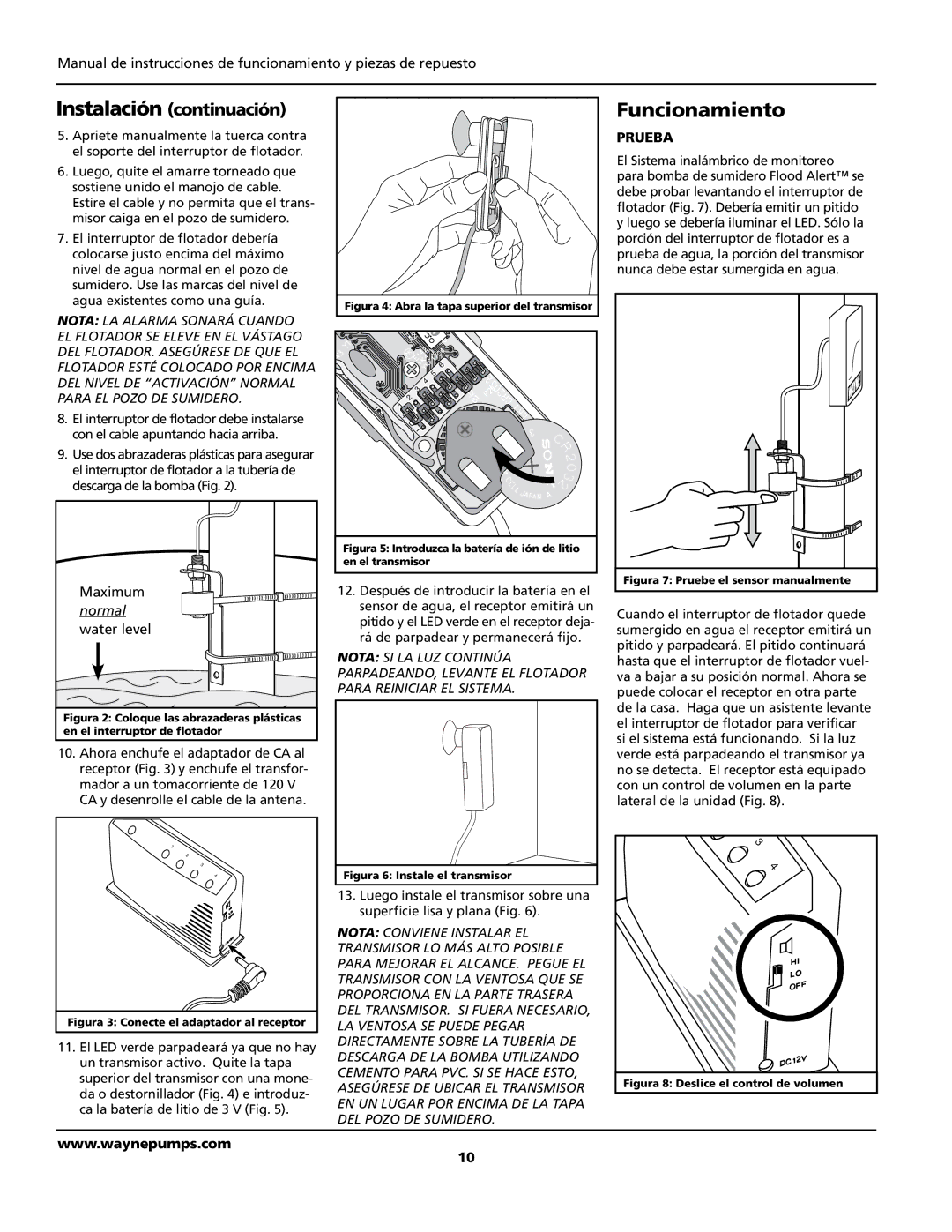
5.Apriete manualmente la tuerca contra el soporte del interruptor de flotador.

6.Luego, quite el amarre torneado que sostiene unido el manojo de cable. Estire el cable y no permita que el trans- misor caiga en el pozo de sumidero.

7.El interruptor de flotador debería colocarse justo encima del máximo nivel de agua normal en el pozo de sumidero. Use las marcas del nivel de agua existentes como una guía.

notA: LA ALARMA SONARÁ CUANDO EL FLOTADOR SE ELEVE EN EL VÁSTAGO DEL FLOTADOR. ASEGÚRESE DE QUE EL FLOTADOR ESTÉ COLOCADO POR ENCIMA DEL NIVEL DE “ACTIVACIÓN” NORMAL PARA EL POZO DE SUMIDERO.

8.El interruptor de flotador debe instalarse con el cable apuntando hacia arriba.

9.Use dos abrazaderas plásticas para asegurar el interruptor de flotador a la tubería de descarga de la bomba (Fig. 2).

Maximum normal water level

Figura 2: Coloque las abrazaderas plásticas en el interruptor de flotador

10.Ahora enchufe el adaptador de CA al receptor (Fig. 3) y enchufe el transfor- mador a un tomacorriente de 120 V

CA y desenrolle el cable de la antena.

1

2

3

4

Figura 3: Conecte el adaptador al receptor

11.El LED verde parpadeará ya que no hay un transmisor activo. Quite la tapa superior del transmisor con una mone- da o destornillador (Fig. 4) e introduz-

ca la batería de litio de 3 V (Fig. 5).

Figura 4: Abra la tapa superior del transmisor

6 5 4 3

2 1

Figura 5: Introduzca la batería de ión de litio en el transmisor

12.Después de introducir la batería en el sensor de agua, el receptor emitirá un pitido y el LED verde en el receptor deja- rá de parpadear y permanecerá fijo.

NOTA: SI LA LUZ CONTINÚA PARPADEANDO, LEVANTE EL FLOTADOR PARA REINICIAR EL SISTEMA.

Figura 6: Instale el transmisor

13.Luego instale el transmisor sobre una superficie lisa y plana (Fig. 6).

NOTA: CONVIENE INSTALAR EL TRANSMISOR LO MÁS ALTO POSIBLE PARA MEJORAR EL ALCANCE. PEGUE EL TRANSMISOR CON LA VENTOSA QUE SE PROPORCIONA EN LA PARTE TRASERA DEL TRANSMISOR. SI FUERA NECESARIO, LA VENTOSA SE PUEDE PEGAR DIRECTAMENTE SOBRE LA TUBERÍA DE DESCARGA DE LA BOMBA UTILIZANDO CEMENTO PARA PVC. SI SE HACE ESTO, ASEGÚRESE DE UBICAR EL TRANSMISOR EN UN LUGAR POR ENCIMA DE LA TAPA DEL POZO DE SUMIDERO.

Funcionamiento

PRUEBA

El Sistema inalámbrico de monitoreo para bomba de sumidero Flood Alert™ se debe probar levantando el interruptor de flotador (Fig. 7). Debería emitir un pitido y luego se debería iluminar el LED. Sólo la porción del interruptor de flotador es a prueba de agua, la porción del transmisor nunca debe estar sumergida en agua.

Figura 7: Pruebe el sensor manualmente

Cuando el interruptor de flotador quede sumergido en agua el receptor emitirá un pitido y parpadeará. El pitido continuará hasta que el interruptor de flotador vuel- va a bajar a su posición normal. Ahora se puede colocar el receptor en otra parte de la casa. Haga que un asistente levante el interruptor de flotador para verificar si el sistema está funcionando. Si la luz verde está parpadeando el transmisor ya no se detecta. El receptor está equipado con un control de volumen en la parte lateral de la unidad (Fig. 8).

3

4

Figura 8: Deslice el control de volumen

www.waynepumps.com

10

Page 10
Image 10
Wayne WSA120, 370700-001 warranty Funcionamiento, Prueba

370700-001, WSA120 specifications

Wayne 370700-001 is a sophisticated and robust solution designed for modern fuel dispensing systems. This model is part of Wayne's continuing commitment to providing advanced technology and reliable performance in the fueling industry. The WSA120 is engineered to meet the stringent demands of both retail and commercial markets, ensuring efficient transactions and enhanced customer experience.

One of the main features of the Wayne 370700-001 is its state-of-the-art electronic control system, which is designed for optimal performance and user-friendly operation. This system supports both contactless and traditional payment methods, accommodating a wide range of consumer preferences. The integration of advanced payment technologies not only enhances convenience but also ensures secure transactions, thereby reducing the risk of fraud.

The WSA120 boasts a durable construction designed to withstand harsh environmental conditions. Its robust design includes corrosion-resistant materials that enhance longevity and reduce maintenance costs. This durability is crucial for operators looking to maximize uptime and minimize disruptions caused by equipment failure.

In terms of technology, the Wayne 370700-001 is equipped with an intuitive touchscreen interface that provides customers with a clear and straightforward menu for fuel selection and payment processing. This interface can be customized to display promotions and advertisements, allowing operators to drive additional revenue through upselling and engaging advertisements.

Another significant characteristic of the WSA120 is its compatibility with various fuel types, ranging from gasoline to high ethanol blends. This versatility makes it suitable for a broad range of fueling applications, whether for traditional gas stations or more specialized refueling sites.

The Wayne 370700-001 also includes sophisticated diagnostics and reporting capabilities, allowing operators to monitor performance in real-time. This feature facilitates quick identification of issues, aiding in proactive maintenance and ensuring maximum operational efficiency.

Moreover, the Wayne 370700-001 supports remote management features, enabling operators to manage their dispensing systems from a distance. This connectivity not only streamlines operations but also enhances customer service by allowing for quicker response times to any issues that may arise.

In conclusion, the Wayne 370700-001 and WSA120 are engineered to provide a reliable, efficient, and user-friendly fuel dispensing solution. Their advanced features, durable construction, and extensive technology support make them an essential asset for any fueling operation looking to thrive in a competitive landscape.