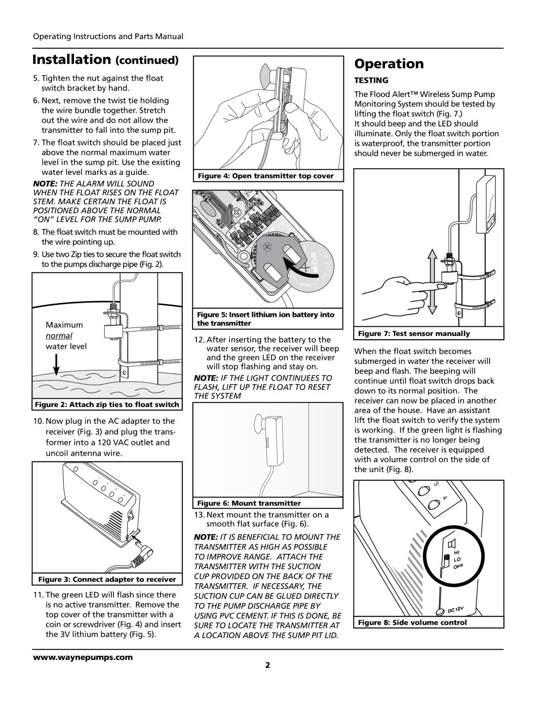
370700-001, WSA120 specifications
Wayne 370700-001 is a sophisticated and robust solution designed for modern fuel dispensing systems. This model is part of Wayne's continuing commitment to providing advanced technology and reliable performance in the fueling industry. The WSA120 is engineered to meet the stringent demands of both retail and commercial markets, ensuring efficient transactions and enhanced customer experience.One of the main features of the Wayne 370700-001 is its state-of-the-art electronic control system, which is designed for optimal performance and user-friendly operation. This system supports both contactless and traditional payment methods, accommodating a wide range of consumer preferences. The integration of advanced payment technologies not only enhances convenience but also ensures secure transactions, thereby reducing the risk of fraud.
The WSA120 boasts a durable construction designed to withstand harsh environmental conditions. Its robust design includes corrosion-resistant materials that enhance longevity and reduce maintenance costs. This durability is crucial for operators looking to maximize uptime and minimize disruptions caused by equipment failure.
In terms of technology, the Wayne 370700-001 is equipped with an intuitive touchscreen interface that provides customers with a clear and straightforward menu for fuel selection and payment processing. This interface can be customized to display promotions and advertisements, allowing operators to drive additional revenue through upselling and engaging advertisements.
Another significant characteristic of the WSA120 is its compatibility with various fuel types, ranging from gasoline to high ethanol blends. This versatility makes it suitable for a broad range of fueling applications, whether for traditional gas stations or more specialized refueling sites.
The Wayne 370700-001 also includes sophisticated diagnostics and reporting capabilities, allowing operators to monitor performance in real-time. This feature facilitates quick identification of issues, aiding in proactive maintenance and ensuring maximum operational efficiency.
Moreover, the Wayne 370700-001 supports remote management features, enabling operators to manage their dispensing systems from a distance. This connectivity not only streamlines operations but also enhances customer service by allowing for quicker response times to any issues that may arise.
In conclusion, the Wayne 370700-001 and WSA120 are engineered to provide a reliable, efficient, and user-friendly fuel dispensing solution. Their advanced features, durable construction, and extensive technology support make them an essential asset for any fueling operation looking to thrive in a competitive landscape.

