8 | INSTALLATION |
BUILT-IN GAS LINE LOCATIONS
GENERAL CONSTRUCTION DETAILS
•Summit®
•Provide access for a corrugated gas line depending on the location of the side burner in relation to your main gas supply and regulator position.
•Area should be kept clear of sharp, jagged, or extremely abrasive surfaces to avoid possible damage to gas supply lines. Exercise caution when pulling gas lines through
•A 3/8 inch (9.52 mm) stainless steel corrugated gas line (NOT INCLUDED) should be used to connect the side burner to the bulkhead accessory coupling.
CAUTION: 3/8 inch (9.52 mm) stainless steel corrugated gas line must not exceed 58 inches (147 cm) in length. A longer hose could cause an improper pressure drop.
WARNING: Do not use a rubber gas hose.
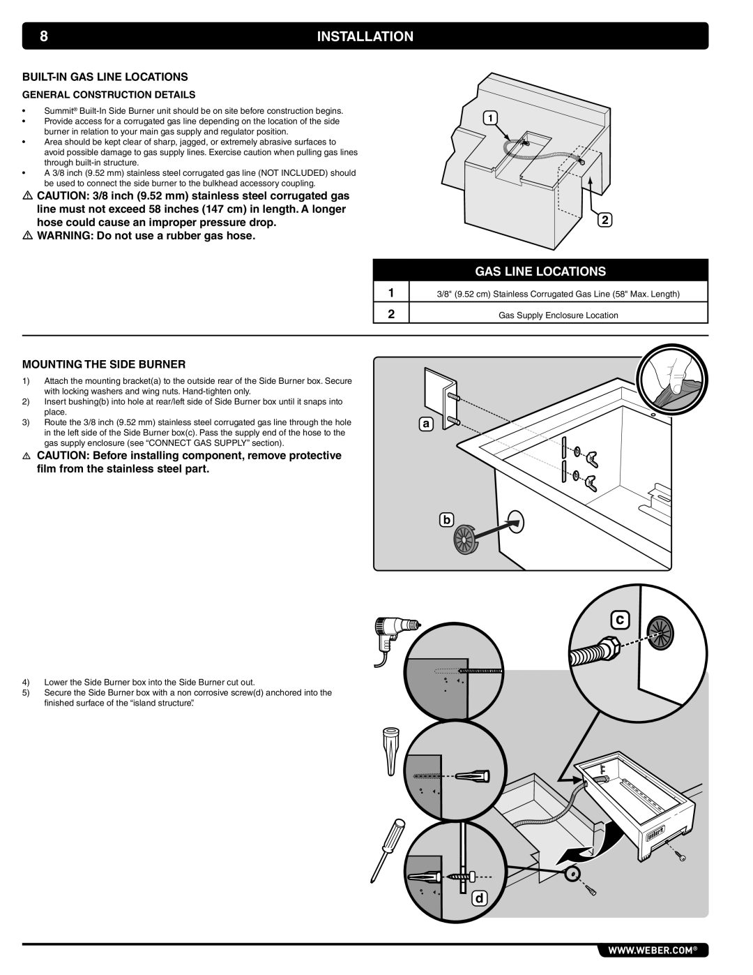
1
2
GAS LINE LOCATIONS
13/8" (9.52 cm) Stainless Corrugated Gas Line (58" Max. Length)
2 | Gas Supply Enclosure Location |
MOUNTING THE SIDE BURNER
1)Attach the mounting bracket(a) to the outside rear of the Side Burner box. Secure with locking washers and wing nuts.
2) Insert bushing(b) into hole at rear/left side of Side Burner box until it snaps into place.
3) Route the 3/8 inch (9.52 mm) stainless steel corrugated gas line through the holea in the left side of the Side Burner box(c). Pass the supply end of the hose to the
gas supply enclosure (see “CONNECT GAS SUPPLY” section).
CAUTION: Before installing component, remove protective film from the stainless steel part.
b
c
4) Lower the Side Burner box into the Side Burner cut out.
5) Secure the Side Burner box with a non corrosive screw(d) anchored into the finished surface of the “island structure”.
d
WWW.WEBER.COM®