5.Wind the line evenly and tightly onto the spool. Wind in the direction of the arrows found on the spool.
6.Push the lines into the notches, leaving 3 to 5 inches (7
7.Insert the lines into the the exit holes in the hub as shown in the illustration.
8.Align the notches with the line exit holes.
9.Push spool into hub until it snaps into place.
10.Pull the lines extending outside of the hub to release the lines from the notches.
LINE REPLACEMENT
(Models W25CF, W25SF, W25CFK, W25SFK)
![]() WARNING: For models W25CB, W25SB, W25CBK, W25SBK, use only 0.080 inch (2 mm) diameter line. Other sizes of line will not advance properly and will result in improper cutting head function or can cause serious injury. For models W25CF, W25SF, W25CFK, W25SFK, use only 0.095 inch (2.4 mm) diame- ter cut length line. Do not use other materials such as wire, string, rope, etc. Wire can break off during cutting and become a dangerous pro- jectile that can cause serious injury.
WARNING: For models W25CB, W25SB, W25CBK, W25SBK, use only 0.080 inch (2 mm) diameter line. Other sizes of line will not advance properly and will result in improper cutting head function or can cause serious injury. For models W25CF, W25SF, W25CFK, W25SFK, use only 0.095 inch (2.4 mm) diame- ter cut length line. Do not use other materials such as wire, string, rope, etc. Wire can break off during cutting and become a dangerous pro- jectile that can cause serious injury.
For unit to operate properly, the cutting line should be replaced when line becomes worn toless than 3inches inlength fromthe edgeof each side of the cutting head.
1.Remove and discard worn line before installing new line.
2.Clean entire surface of cutting head.
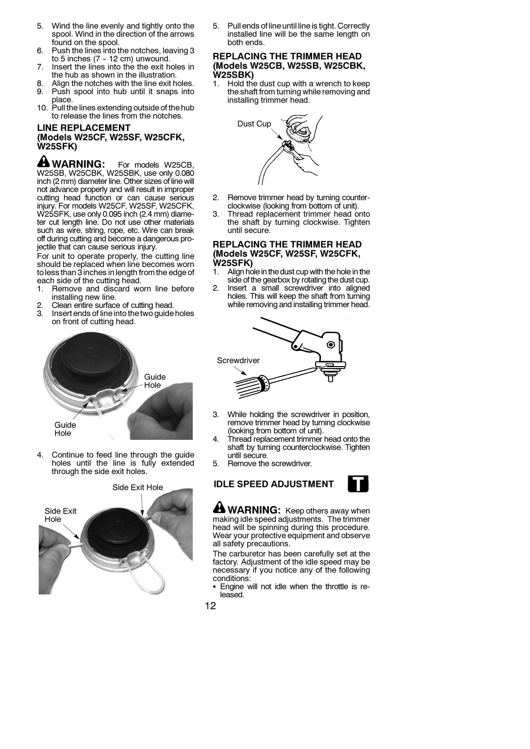
3.Insert ends of lineinto thetwo guideholes on front of cutting head.
Guide
![]() Hole
Hole
Guide
Hole
4.Continue to feed line through the guide holes until the line is fully extended through the side exit holes.
Side Exit Hole
Side Exit
Hole
5.Pullends of lineuntillineis tight. Correctly installed line will be the same length on both ends.
REPLACING THE TRIMMER HEAD (Models W25CB, W25SB, W25CBK, W25SBK)
1.Hold the dust cup with a wrench to keep the shaft from turning while removing and installing trimmer head.
Dust Cup
2.Remove trimmer head by turning counter- clockwise (looking from bottom of unit).
3.Thread replacement trimmer head onto the shaft by turning clockwise. Tighten until secure.
REPLACING THE TRIMMER HEAD (Models W25CF, W25SF, W25CFK, W25SFK)
1.Alignholeinthedust cupwith thehole inthe side of the gearbox by rotatingthe dust cup.
2.Insert a small screwdriver into aligned holes. This will keep the shaft from turning while removing and installing trimmer head.
Screwdriver
3.While holding the screwdriver in position, remove trimmer head by turning clockwise (looking from bottom of unit).
4.Thread replacement trimmer head onto the shaft by turning counterclockwise. Tighten until secure.
5.Remove the screwdriver.
IDLE SPEED ADJUSTMENT
![]() WARNING: Keep others away when making idle speed adjustments. The trimmer head will be spinning during this procedure. Wear your protective equipment and observe all safety precautions.
WARNING: Keep others away when making idle speed adjustments. The trimmer head will be spinning during this procedure. Wear your protective equipment and observe all safety precautions.
The carburetor has been carefully set at the factory. Adjustment of the idle speed may be necessary if you notice any of the following conditions:
SEngine will not idle when the throttle is re- leased.
12