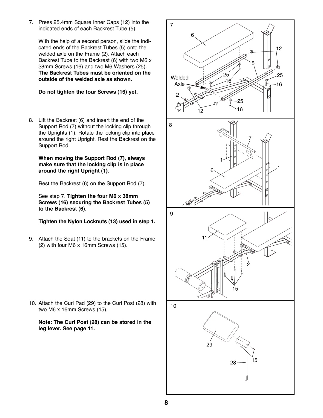
7. | Press 25.4mm Square Inner Caps (12) into the | 7 |
|
|
|
| indicated ends of each Backrest Tube (5). |
|
|
| |
|
|
|
|
| |
|
|
| 6 |
|
|
| With the help of a second person, slide the indi- |
|
|
|
|
| cated ends of the Backrest Tubes (5) onto the |
|
|
| 12 |
| welded axle on the Frame (2). Attach each |
|
|
|
|
| Backrest Tube to the Backrest (6) with two M6 x |
|
|
| 5 |
| 38mm Screws (16) and two M6 Washers (25). |
|
|
| |
|
|
|
|
| |
| The Backrest Tubes must be oriented on the | Welded | 25 |
| 25 |
| outside of the welded axle as shown. |
| |||
| 16 |
| |||
|
| Axle | 16 | ||
|
|
|
| ||
| Do not tighten the four Screws (16) yet. | 2 |
|
|
|
|
|
|
|
| |
|
|
|
| 25 |
|
|
|
| 12 | 16 |
|
8. | Lift the Backrest (6) and insert the end of the | 8 |
|
|
|
| Support Rod (7) without the locking clip through |
|
|
| |
| the Uprights (1). Rotate the locking clip into place |
|
|
| 7 |
| around the right Upright. Rest the Backrest on the |
|
|
| |
| Support Rod. |
|
|
|
|
| When moving the Support Rod (7), always |
| 1 |
|
|
| make sure that the locking clip is in place |
|
|
| |
|
| 6 |
| 1 | |
| around the right Upright (1). |
|
| ||
|
|
|
| ||
| Rest the Backrest (6) on the Support Rod (7). |
|
|
|
|
| See step 7. Tighten the four M6 x 38mm |
|
|
|
|
| Screws (16) securing the Backrest Tubes (5) |
|
|
|
|
| to the Backrest (6). | 9 |
|
|
|
|
|
|
|
| |
| Tighten the Nylon Locknuts (13) used in step 1. |
|
|
|
|
9. | Attach the Seat (11) to the brackets on the Frame |
| 11 |
|
|
| (2) with four M6 x 16mm Screws (15). |
|
|
|
|
|
|
|
|
| 2 |
|
|
|
| 15 |
|
10. | Attach the Curl Pad (29) to the Curl Post (28) with | 10 |
|
|
|
| two M6 x 16mm Screws (15). |
|
|
| |
|
|
|
|
| |
| Note: The Curl Post (28) can be stored in the |
|
|
|
|
| leg lever. See page 11. |
|
|
|
|
|
|
| 29 |
|
|
|
|
|
| 28 | 15 |
|
|
|
|
| |
|
| 8 |
|
|
|
