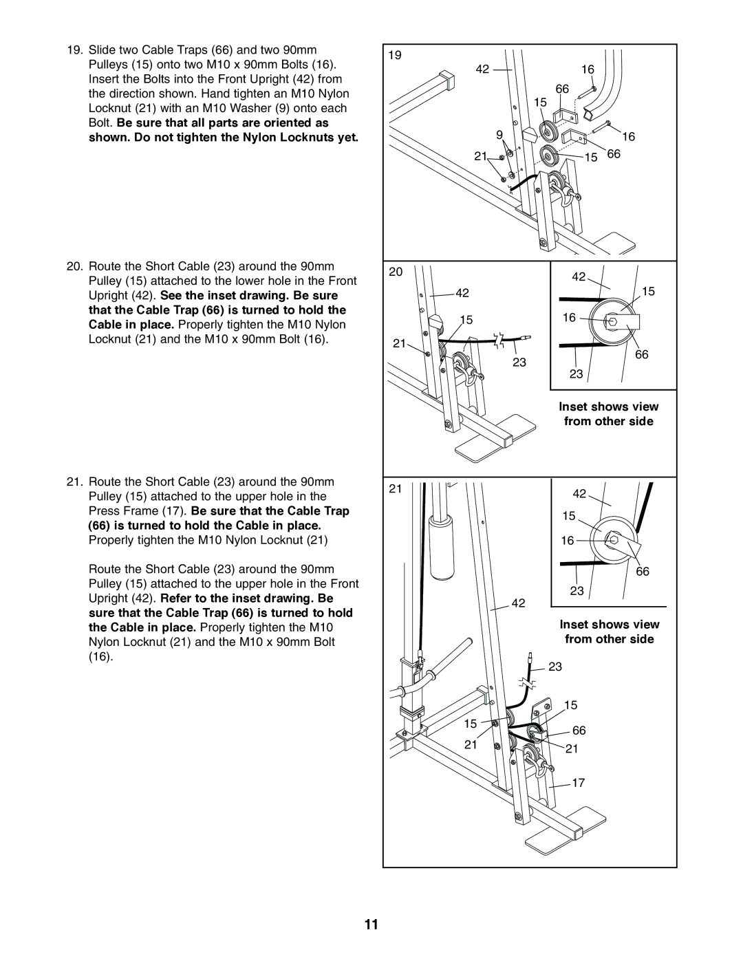
19. Slide two Cable Traps (66) and two 90mm | 19 |
|
|
Pulleys (15) onto two M10 x 90mm Bolts (16). |
|
| |
42 | 16 |
| |
Insert the Bolts into the Front Upright (42) from |
| ||
| 66 |
| |
the direction shown. Hand tighten an M10 Nylon |
|
| |
| 15 |
| |
Locknut (21) with an M10 Washer (9) onto each |
|
| |
|
|
| |
Bolt. Be sure that all parts are oriented as | 9 |
|
|
shown. Do not tighten the Nylon Locknuts yet. |
| 16 | |
| 21 | 15 | 66 |
20. Route the Short Cable (23) around the 90mm | 20 | 42 |
|
Pulley (15) attached to the lower hole in the Front |
| ||
|
| ||
42 |
| 15 | |
Upright (42). See the inset drawing. Be sure |
| ||
that the Cable Trap (66) is turned to hold the | 15 | 16 |
|
Cable in place. Properly tighten the M10 Nylon |
| ||
|
|
| |
Locknut (21) and the M10 x 90mm Bolt (16). | 21 |
|
|
|
| 66 | |
|
| 23 | |
|
|
| |
|
| 23 |
|
|
| Inset shows view | |
|
| from other side | |
21. Route the Short Cable (23) around the 90mm | 21 | 42 |
|
Pulley (15) attached to the upper hole in the |
| ||
|
| ||
Press Frame (17). Be sure that the Cable Trap |
| 15 |
|
(66) is turned to hold the Cable in place. |
|
| |
|
|
| |
Properly tighten the M10 Nylon Locknut (21) |
| 16 |
|
Route the Short Cable (23) around the 90mm |
|
| 66 |
Pulley (15) attached to the upper hole in the Front |
| 23 |
|
Upright (42). Refer to the inset drawing. Be |
|
| |
| 42 |
| |
sure that the Cable Trap (66) is turned to hold |
|
| |
| Inset shows view | ||
the Cable in place. Properly tighten the M10 |
| ||
Nylon Locknut (21) and the M10 x 90mm Bolt |
| from other side | |
(16). |
| 23 |
|
|
|
| |
|
| 15 |
|
| 15 | 66 |
|
|
|
| |
| 21 | 21 |
|
|
|
| |
|
| 17 |
|
11