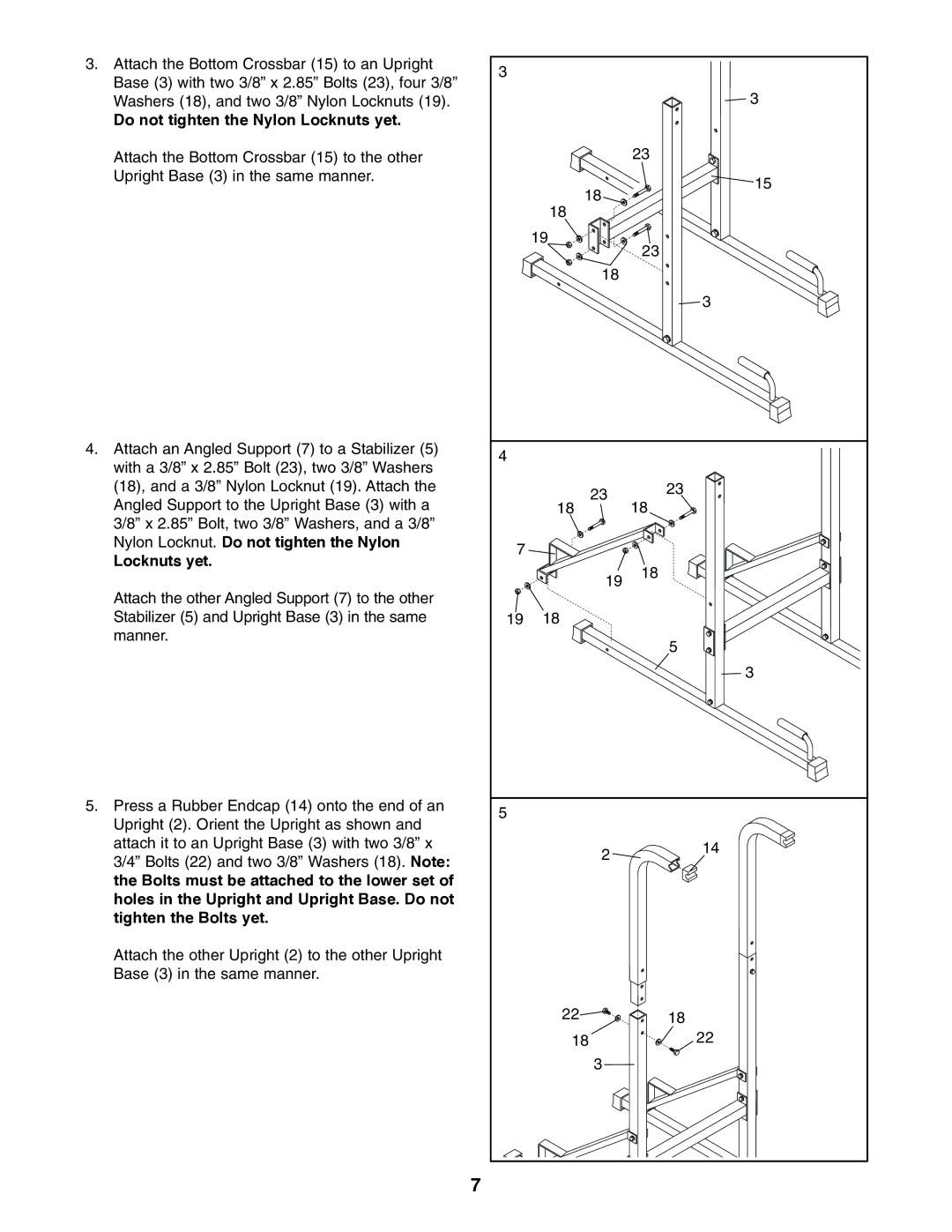
3.Attach the Bottom Crossbar (15) to an Upright Base (3) with two 3/8” x 2.85” Bolts (23), four 3/8” Washers (18), and two 3/8” Nylon Locknuts (19).
Do not tighten the Nylon Locknuts yet.
Attach the Bottom Crossbar (15) to the other Upright Base (3) in the same manner.
4.Attach an Angled Support (7) to a Stabilizer (5) with a 3/8” x 2.85” Bolt (23), two 3/8” Washers (18), and a 3/8” Nylon Locknut (19). Attach the Angled Support to the Upright Base (3) with a 3/8” x 2.85” Bolt, two 3/8” Washers, and a 3/8” Nylon Locknut. Do not tighten the Nylon
Locknuts yet.
Attach the other Angled Support (7) to the other Stabilizer (5) and Upright Base (3) in the same manner.
5.Press a Rubber Endcap (14) onto the end of an Upright (2). Orient the Upright as shown and attach it to an Upright Base (3) with two 3/8” x 3/4” Bolts (22) and two 3/8” Washers (18). Note: the Bolts must be attached to the lower set of holes in the Upright and Upright Base. Do not tighten the Bolts yet.
Attach the other Upright (2) to the other Upright Base (3) in the same manner.
7
3 |
|
|
|
| 3 |
|
| 23 |
| 18 | 15 |
|
| |
| 18 |
|
| 19 | 23 |
|
| |
| 18 |
|
|
| 3 |
4 |
|
|
| 23 | 23 |
| 18 | |
| 18 | |
7 |
|
|
| 19 | 18 |
|
| |
19 | 18 |
|
|
| 5 |
|
| 3 |
5 |
|
|
| 2 | 14 |
|
| |
| 22 | 18 |
| 18 | 22 |
| 3 |
|
