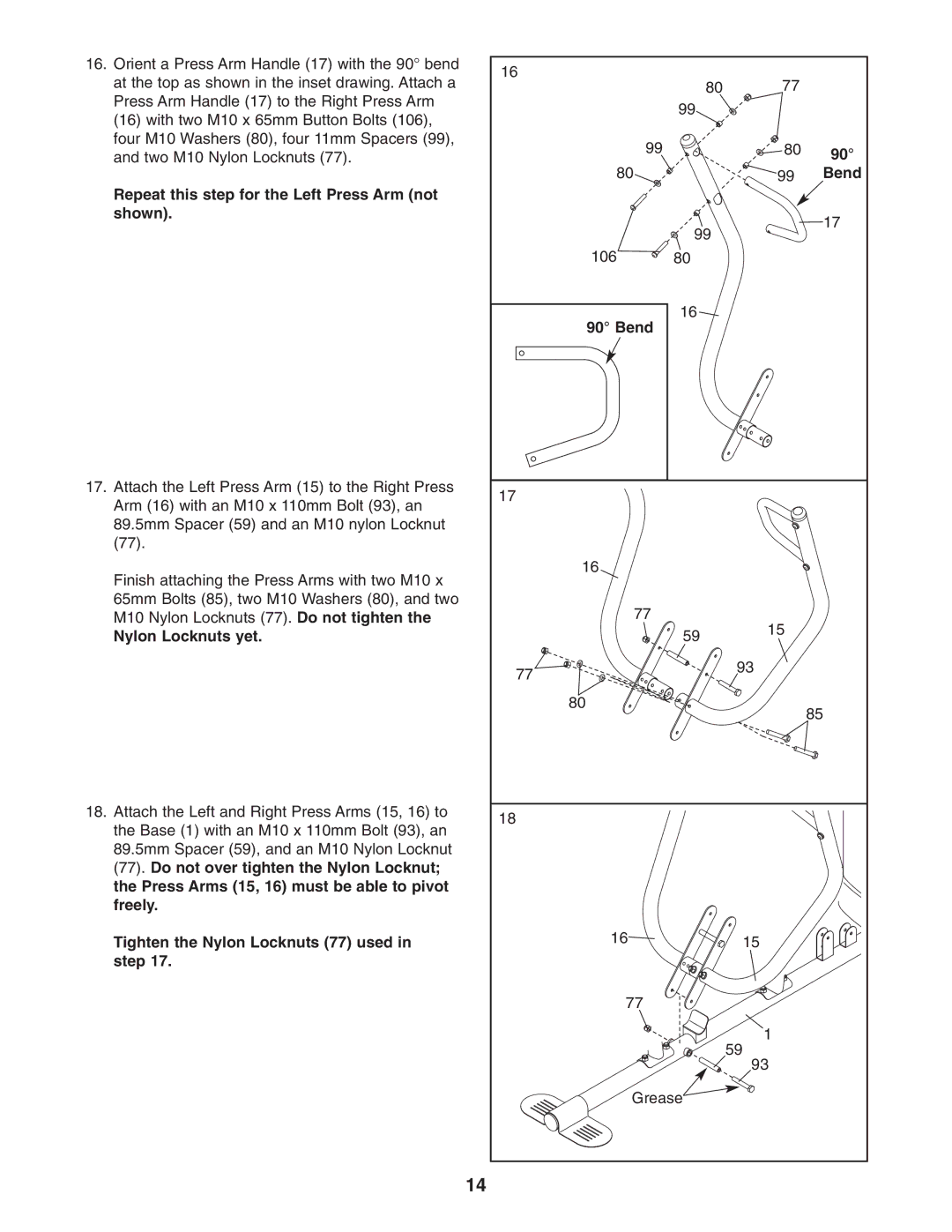
16.Orient a Press Arm Handle (17) with the 90° bend at the top as shown in the inset drawing. Attach a Press Arm Handle (17) to the Right Press Arm (16) with two M10 x 65mm Button Bolts (106), four M10 Washers (80), four 11mm Spacers (99), and two M10 Nylon Locknuts (77).
Repeat this step for the Left Press Arm (not shown).
17.Attach the Left Press Arm (15) to the Right Press Arm (16) with an M10 x 110mm Bolt (93), an 89.5mm Spacer (59) and an M10 nylon Locknut (77).
Finish attaching the Press Arms with two M10 x 65mm Bolts (85), two M10 Washers (80), and two M10 Nylon Locknuts (77). Do not tighten the
Nylon Locknuts yet.
18.Attach the Left and Right Press Arms (15, 16) to the Base (1) with an M10 x 110mm Bolt (93), an 89.5mm Spacer (59), and an M10 Nylon Locknut (77). Do not over tighten the Nylon Locknut; the Press Arms (15, 16) must be able to pivot freely.
Tighten the Nylon Locknuts (77) used in step 17.
16 | 80 | 77 |
|
|
| ||
| 99 |
|
|
99 |
| 80 | 90° |
|
|
| |
80 |
| 99 | Bend |
| 99 |
| 17 |
|
|
| |
106 | 80 |
|
|
90° Bend | 16 |
|
|
|
|
| |
17 |
|
|
|
16 |
|
|
|
77 |
| 15 |
|
| 59 |
| |
|
|
| |
77 |
| 93 |
|
|
|
| |
80 |
|
| 85 |
|
|
| |
18 |
|
|
|
16 |
| 15 |
|
77 |
|
|
|
|
| 1 |
|
|
| 59 |
|
|
| 93 |
|
Grease |
|
| |
14
