Frame Assembly | 1 |
|
|
|
|
|
|
| |
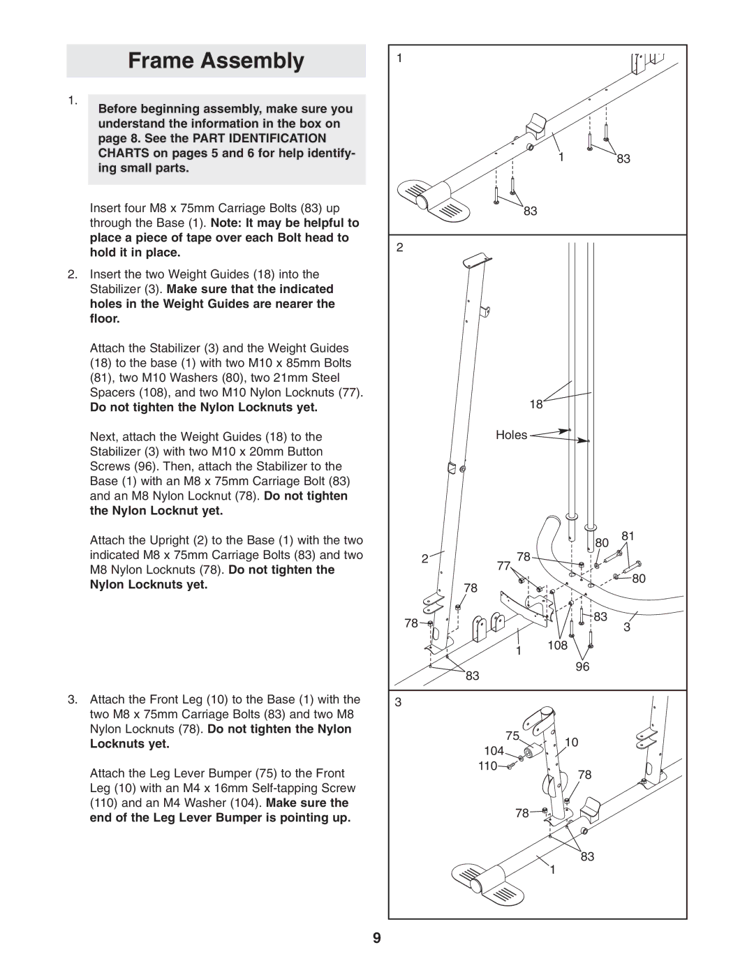
1. |
|
|
|
|
Before beginning assembly, make sure you |
|
|
|
|
understand the information in the box on |
|
|
|
|
page 8. See the PART IDENTIFICATION |
|
|
|
|
CHARTS on pages 5 and 6 for help identify- |
|
| 1 | 83 |
ing small parts. |
|
| ||
|
|
|
| |
Insert four M8 x 75mm Carriage Bolts (83) up |
| 83 |
|
|
through the Base (1). Note: It may be helpful to |
|
|
|
|
place a piece of tape over each Bolt head to | 2 |
|
|
|
hold it in place. |
|
|
| |
|
|
|
| |
2. Insert the two Weight Guides (18) into the |
|
|
|
|
Stabilizer (3). Make sure that the indicated |
|
|
|
|
holes in the Weight Guides are nearer the |
|
|
|
|
floor. |
|
|
|
|
Attach the Stabilizer (3) and the Weight Guides |
|
|
|
|
(18) to the base (1) with two M10 x 85mm Bolts |
|
|
|
|
(81), two M10 Washers (80), two 21mm Steel |
|
|
|
|
Spacers (108), and two M10 Nylon Locknuts (77). |
| 18 |
|
|
Do not tighten the Nylon Locknuts yet. |
|
|
| |
Next, attach the Weight Guides (18) to the |
| Holes |
|
|
Stabilizer (3) with two M10 x 20mm Button |
|
|
|
|
Screws (96). Then, attach the Stabilizer to the |
|
|
|
|
Base (1) with an M8 x 75mm Carriage Bolt (83) |
|
|
|
|
and an M8 Nylon Locknut (78). Do not tighten |
|
|
|
|
the Nylon Locknut yet. |
|
|
|
|
Attach the Upright (2) to the Base (1) with the two |
|
| 80 | 81 |
indicated M8 x 75mm Carriage Bolts (83) and two | 2 | 78 |
|
|
M8 Nylon Locknuts (78). Do not tighten the |
| 77 |
| 80 |
|
|
| ||
Nylon Locknuts yet. |
| 78 |
| |
|
|
| ||
| 78 |
| 83 | 3 |
|
|
| ||
|
|
|
| |
|
| 1 | 108 |
|
|
|
|
| |
|
| 83 | 96 |
|
|
|
|
| |
3. Attach the Front Leg (10) to the Base (1) with the | 3 |
|
|
|
two M8 x 75mm Carriage Bolts (83) and two M8 |
|
|
|
|
Nylon Locknuts (78). Do not tighten the Nylon |
| 75 | 10 |
|
Locknuts yet. |
|
| ||
| 104 |
| ||
|
|
|
| |
Attach the Leg Lever Bumper (75) to the Front |
| 110 | 78 |
|
|
|
| ||
Leg (10) with an M4 x 16mm |
|
|
|
|
(110) and an M4 Washer (104). Make sure the |
| 78 |
|
|
end of the Leg Lever Bumper is pointing up. |
|
|
| |
|
|
|
| |
|
|
| 83 |
|
|
|
| 1 |
|
| 9 |
|
|
|