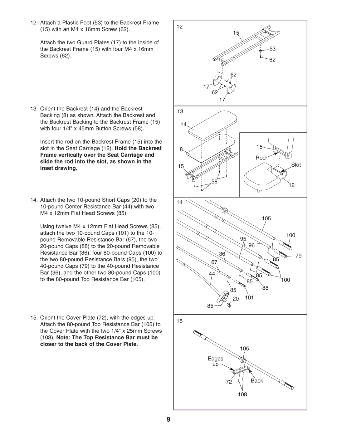
12. Attach a Plastic Foot (53) to the Backrest Frame | 12 |
|
|
|
(15) with an M4 x 16mm Screw (62). | 15 |
|
| |
|
|
| ||
|
|
|
| |
Attach the two Guard Plates (17) to the inside of |
|
|
|
|
the Backrest Frame (15) with four M4 x 16mm |
|
| 53 |
|
Screws (62). |
|
| 62 |
|
|
|
|
| |
|
| 62 |
|
|
|
| 17 |
|
|
|
| 62 |
|
|
|
| 17 |
|
|
13. Orient the Backrest (14) and the Backrest | 13 |
|
|
|
Backing (8) as shown. Attach the Backrest and |
|
|
| |
|
|
|
| |
the Backrest Backing to the Backrest Frame (15) | 14 |
|
|
|
with four 1/4” x 45mm Button Screws (58). |
|
|
| |
|
|
|
| |
Insert the rod on the Backrest Frame (15) into the |
|
| 15 |
|
slot in the Seat Carriage (12). Hold the Backrest | 8 |
|
| |
Frame vertically over the Seat Carriage and |
|
| Rod |
|
slide the rod into the slot, as shown in the |
|
|
| |
15 |
|
| Slot | |
inset drawing. |
|
| ||
|
|
|
| |
|
| 58 |
| 12 |
|
|
|
| |
14. Attach the two | 14 |
|
|
|
|
|
| ||
|
|
|
| |
M4 x 12mm Flat Head Screws (85). |
|
| 105 |
|
|
|
|
| |
Using twelve M4 x 12mm Flat Head Screws (85), |
|
|
|
|
attach the two |
|
| 95 | 100 |
pound Removable Resistance Bar (67), the two |
|
| ||
|
|
| ||
|
| 96 |
| |
Resistance Bar (36), four |
| 36 |
| 79 |
the two |
|
| 85 | |
| 67 |
| ||
|
|
| ||
|
|
|
| |
Bar (96), and the other two |
| 44 | 85 |
|
to the |
|
| 100 | |
|
| 85 | ||
|
| 85 | 88 |
|
|
|
|
| |
|
| 20 | 101 |
|
|
| 85 |
|
|
15. Orient the Cover Plate (72), with the edges up. | 15 |
|
|
|
Attach the |
|
|
| |
|
|
|
| |
the Cover Plate with the two 1/4” x 25mm Screws |
|
|
|
|
(108). Note: The Top Resistance Bar must be |
|
|
|
|
closer to the back of the Cover Plate. |
|
| 105 |
|
|
|
|
| |
|
| Edges |
|
|
|
| up |
|
|
|
| 72 | Back |
|
|
| 108 |
| |
9