TROUBLESHOOTING
Most treadmill problems can be solved by following the steps below. Find the symptom that applies, and follow the steps listed. If further assistance is needed, please call our Customer Service Department toll- free at
PROBLEM: The power does not turn on
SOLUTION: a. Make sure that the power cord is plugged into a surge suppressor, and that the surge suppressor is plugged into a properly grounded outlet (see page 9). Use only a
b. After the power cord has been plugged in, make sure that the key is fully inserted into the console.
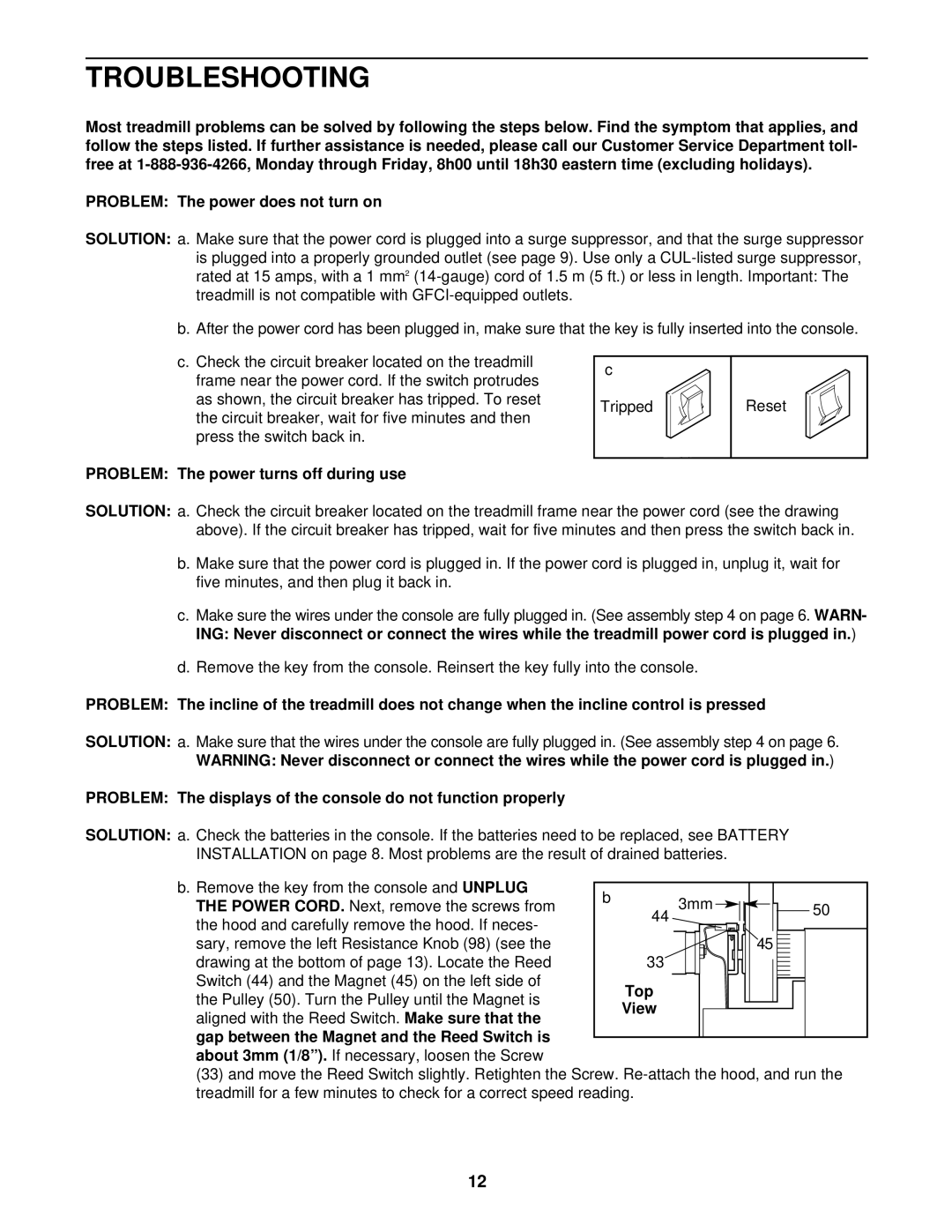
c.Check the circuit breaker located on the treadmill frame near the power cord. If the switch protrudes as shown, the circuit breaker has tripped. To reset the circuit breaker, wait for five minutes and then press the switch back in.
c
Tripped
Reset
PROBLEM: The power turns off during use
SOLUTION: a. Check the circuit breaker located on the treadmill frame near the power cord (see the drawing above). If the circuit breaker has tripped, wait for five minutes and then press the switch back in.
b.Make sure that the power cord is plugged in. If the power cord is plugged in, unplug it, wait for five minutes, and then plug it back in.
c.Make sure the wires under the console are fully plugged in. (See assembly step 4 on page 6. WARN- ING: Never disconnect or connect the wires while the treadmill power cord is plugged in.)
d.Remove the key from the console. Reinsert the key fully into the console.
PROBLEM: The incline of the treadmill does not change when the incline control is pressed
SOLUTION: a. Make sure that the wires under the console are fully plugged in. (See assembly step 4 on page 6. WARNING: Never disconnect or connect the wires while the power cord is plugged in.)
PROBLEM: The displays of the console do not function properly
SOLUTION: a. Check the batteries in the console. If the batteries need to be replaced, see BATTERY INSTALLATION on page 8. Most problems are the result of drained batteries.
b. Remove the key from the console and UNPLUG |
|
|
|
|
|
|
|
|
|
|
|
|
|
|
|
|
|
|
|
|
|
|
|
|
|
|
|
| b |
|
|
|
|
|
|
|
|
|
|
|
|
|
|
|
|
|
|
|
|
|
|
|
|
| |
THE POWER CORD. Next, remove the screws from |
|
|
|
|
|
|
| 3mm |
|
|
|
|
|
|
|
|
|
|
|
|
|
|
|
| |||
|
|
|
|
| 44 |
|
|
|
|
|
|
|
|
|
|
| 50 |
| |||||||||
|
|
|
|
|
|
|
|
|
|
|
|
|
|
|
|
|
|
|
| ||||||||
the hood and carefully remove the hood. If neces- |
|
|
|
|
|
|
|
|
|
|
|
|
|
|
|
|
|
|
|
|
|
|
|
| |||
|
|
|
|
|
|
|
|
|
|
|
|
|
|
|
|
|
|
|
|
|
|
|
| ||||
sary, remove the left Resistance Knob (98) (see the |
|
|
|
|
|
|
|
|
|
|
|
|
|
|
|
|
| 45 |
|
|
|
|
|
| |||
|
|
|
|
|
|
|
|
|
|
|
|
| |||||||||||||||
drawing at the bottom of page 13). Locate the Reed |
|
|
|
| 33 |
|
|
|
|
|
|
|
|
|
|
|
|
|
|
|
|
|
|
|
|
| |
Switch (44) and the Magnet (45) on the left side of |
|
|
|
|
|
|
|
|
|
|
|
|
|
|
|
|
|
|
|
|
|
|
|
|
|
|
|
|
| Top |
|
|
|
|
|
|
|
|
|
|
|
|
|
|
|
|
|
|
|
|
| ||||
the Pulley (50). Turn the Pulley until the Magnet is |
|
|
|
|
|
|
|
|
|
|
|
|
|
|
|
|
|
|
|
|
| ||||||
|
| View |
|
|
|
|
|
|
|
|
|
|
|
|
|
|
|
|
|
|
|
|
| ||||
aligned with the Reed Switch. Make sure that the |
|
|
|
|
|
|
|
|
|
|
|
|
|
|
|
|
|
|
|
|
| ||||||
|
|
|
|
|
|
|
|
|
|
|
|
|
|
|
|
|
|
|
|
|
|
|
|
|
|
| |
|
|
|
|
|
|
|
|
|
|
|
|
|
|
|
|
|
|
|
|
|
|
|
|
|
|
| |
gap between the Magnet and the Reed Switch is |
|
|
|
|
|
|
|
|
|
|
|
|
|
|
|
|
|
|
|
|
|
|
|
|
|
|
|
|
|
|
|
|
|
|
|
|
|
|
|
|
|
|
|
|
|
|
|
|
|
|
|
|
|
| |
about 3mm (1/8”). If necessary, loosen the Screw |
|
|
|
|
|
|
|
|
|
|
|
|
|
|
|
|
|
|
|
|
|
|
|
|
|
|
|
(33)and move the Reed Switch slightly. Retighten the Screw.
12
