ASSEMBLY
Assembly requires two persons. Set the treadmill in a cleared area and remove all packing materials; do not dispose of the packing materials until assembly is completed.
Note: The underside of the treadmill walking belt is coated with
In addition to the included hex keys ![]()
![]()
![]() , assembly requires a phillips screwdriver
, assembly requires a phillips screwdriver ![]()
![]() , an
, an
adjustable wrench ![]() , and wire cutters
, and wire cutters ![]() .
.
To identify the assembly hardware, see the PART IDENTIFICATION CHART in the center of this manual. Some parts may be preassembled. To avoid damaging plastic parts, do not use power tools for assembly.
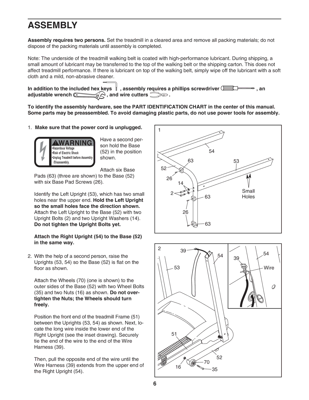
1.Make sure that the power cord is unplugged.
! |
|
|
|
|
|
| Have a second per- |
|
|
|
|
|
| ||
|
|
|
|
|
| son hold the Base | |
|
|
|
|
|
|
| |
|
|
|
|
|
|
| |
|
|
|
|
|
|
| (52) in the position |
|
|
|
|
|
|
| |
|
|
|
|
|
|
| shown. |
|
|
|
|
|
|
| |
|
|
|
|
|
|
|
Attach six Base Pads (63) (three are shown) to the Base (52) with six Base Pad Screws (26).
Identify the Left Upright (53), which has two small holes near the upper end. Hold the Left Upright so the small holes face the direction shown.
Attach the Left Upright to the Base (52) with two Upright Bolts (2) and two Upright Washers (14).
Do not tighten the Upright Bolts yet.
Attach the Right Upright (54) to the Base (52) in the same way.
2.With the help of a second person, raise the Uprights (53, 54) so the Base (52) is flat on the floor as shown.
Attach the Wheels (70) (one is shown) to the outer sides of the Base (52) with two Wheel Bolts (35) and two Nuts (16) as shown. Do not over- tighten the Nuts; the Wheels should turn freely.
Position the front end of the treadmill Frame (51) between the Uprights (53, 54) as shown. Next, lo- cate the long wire inside the lower end of the Right Upright (see the inset drawing). Securely tie the end of the wire to the end of the Wire Harness (39).
Then, pull the opposite end of the wire until the Wire Harness (39) extends from the upper end of the Right Upright (54).
1 |
|
|
|
| 54 |
|
|
| 63 |
| 53 |
| 52 |
|
|
| 26 |
|
|
| 14 |
|
|
| 2 |
| Small |
|
| Holes | |
| 63 |
| |
| 26 |
|
|
| 63 |
|
|
2 | 39 |
| 54 |
| 54 | ||
|
| ||
|
| 39 | |
|
|
| |
| 53 |
| Wire |
51
| 52 | |
16 | 70 | |
35 | ||
|
6