RMM User’s Guide
2. Unit Description
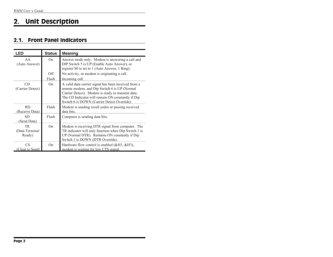
2.1. Front Panel Indicators
LED | Status | Meaning |
AA | On | Answer mode only: Modem is answering a call and |
(Auto Answer) |
| DIP Switch 5 is UP (Enable Auto Answer), or |
|
| register S0 is set to 1 (Auto Answer, 1 Ring). |
| Off | No activity, or modem is originating a call. |
| Flash | Incoming call. |
CD | On | A valid data carrier signal has been received from a |
(Carrier Detect) |
| remote modem, and Dip Switch 6 is UP (Normal |
|
| Carrier Detect). Modem is ready to transmit data. |
|
| The CD Indicator will remain ON constantly if Dip |
|
| Switch 6 is DOWN (Carrier Detect Override). |
RD | Flash | Modem is sending result codes or passing received |
(Receive Data) |
| data bits. |
SD | Flash | Computer is sending data bits. |
(Send Data) |
|
|
TR | On | Modem is receiving DTR signal from computer. The |
(Data Terminal |
| TR indicator will only function when Dip Switch 1 is |
Ready) |
| UP (Normal DTR). Remains ON constantly if Dip |
|
| Switch 1 is DOWN (DTR Override). |
CS | On | Hardware flow control is enabled (&H1, &H3), |
(Clear to Send) |
| modem is waiting for low CTS signal. |
Page 2