Remote Power Boot Switch specifications
The Western Telematic Remote Power Boot Switch is a powerful solution designed for remote management and control of electrical power. This device is particularly useful in industries where equipment needs to be powered on or off from a distance, providing facility managers and operators with increased flexibility and efficiency.One of the main features of this power boot switch is its remote operation capability. Users can manage power from any location through a simple web-based interface or app, allowing for real-time monitoring and control. This feature is essential for organizations with multiple devices or sites, as it minimizes the need for on-site visits to manually reset or reboot equipment. By utilizing a secure network connection, users can access the power boot switch remotely, ensuring their critical systems are always operational.
The Western Telematic switch is built with advanced technologies that enhance its reliability and performance. It supports various communication protocols, including SNMP (Simple Network Management Protocol), Telnet, and SSH, allowing seamless integration into existing network management systems. This compatibility is crucial for enabling automated monitoring, alerts, and control over power states, thus reducing downtime and improving overall operational efficiency.
Another notable characteristic of the Remote Power Boot Switch is its robustness. Designed to withstand challenging environmental conditions, these devices come equipped with durable housings and components, making them suitable for both indoor and outdoor deployments. This durability is essential in preventing failures that could disrupt business operations.
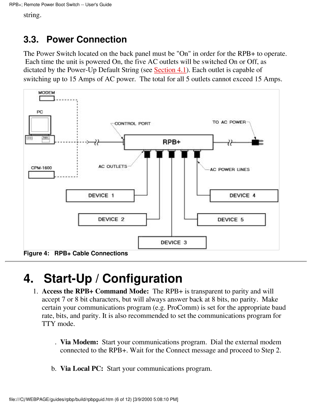
Additionally, the switch features multiple outlets, typically with the capability to control each outlet independently. This functionality allows users to power cycle individual devices without affecting others, providing granular control over power management. The device also includes surge protection, ensuring that connected equipment is safeguarded against power fluctuations and electrical surges.
In conclusion, the Western Telematic Remote Power Boot Switch is an indispensable tool for organizations that require dependable and flexible power management solutions. With its remote operation capabilities, support for various communication protocols, robust design, and multiple outlet controls, it streamlines the management of electrical power, enhances equipment uptime, and ultimately contributes to greater operational efficiency in a variety of settings.

