Table 1 — Interrupting, Closing and Withstand Rating — | Automatic Control | ||||
Robonic Type A |
|
|
|
| |
Robonic |
| rms symmetrical amperes | Voltage Sensing Relays | ||
| |||||
|
| ||||
Continuous |
|
| |||
|
|
|
| Ratings — 1.0 | |
Rating | 600 Vac |
| 480 Vac | 120,208,240 Vac | |
| Input Coil Voltage — 120 volts at 50/60 hertz | ||||
|
|
|
|
| |
30 to 100 amps | 14,000 |
| 14,000 | 18,000 | |
| Contact Rating — 3.0 amperes resistive at 120 volts | ||||
150 to 1000 amps | 22,000 |
| 30,000 | 42,000 | Duty — continuous |
1200 to 3000 amps | 100,000 |
| 100,000 | 125,000 | Operating Temperature Ratings — |
Since type A Robonics employ magnetic only breakers, their interrupting, closing, and withstand ratings are the same value. Under fault conditions, with it’s “normal” breaker closed, a Robonic is required to withstand the energy let through of the normal service protective device while the fault is being cleared. At the same time, should the normal voltage fall below the voltage sensing relay’s selected value, – and if the alternate source were available, the Robonic could transfer before the normal service protective device cleared the fault.
This would require that the Robonic be capable of interrupting the protective device’s let through current. In addition, the Robonic could be required to close in on a fault. Thus can be seen the need for Robonics to have, interrupting, closing and withstand ratings.
The interrupting, closing and withstand ratings shown in Table 1 are those for standard type A Robonics. For higher values, consideration can be given to use of Robonics built with Mark 75,
Table 2 — Maximum Upstream Circuit Protective Devices for
Type A Robonics, All Classes of Loads
Standard Robonic | Maximum Upstream | Maximum Upstream Fuse Rating | Description | ||
| |||||
Continuous | Breaker Frame Size |
|
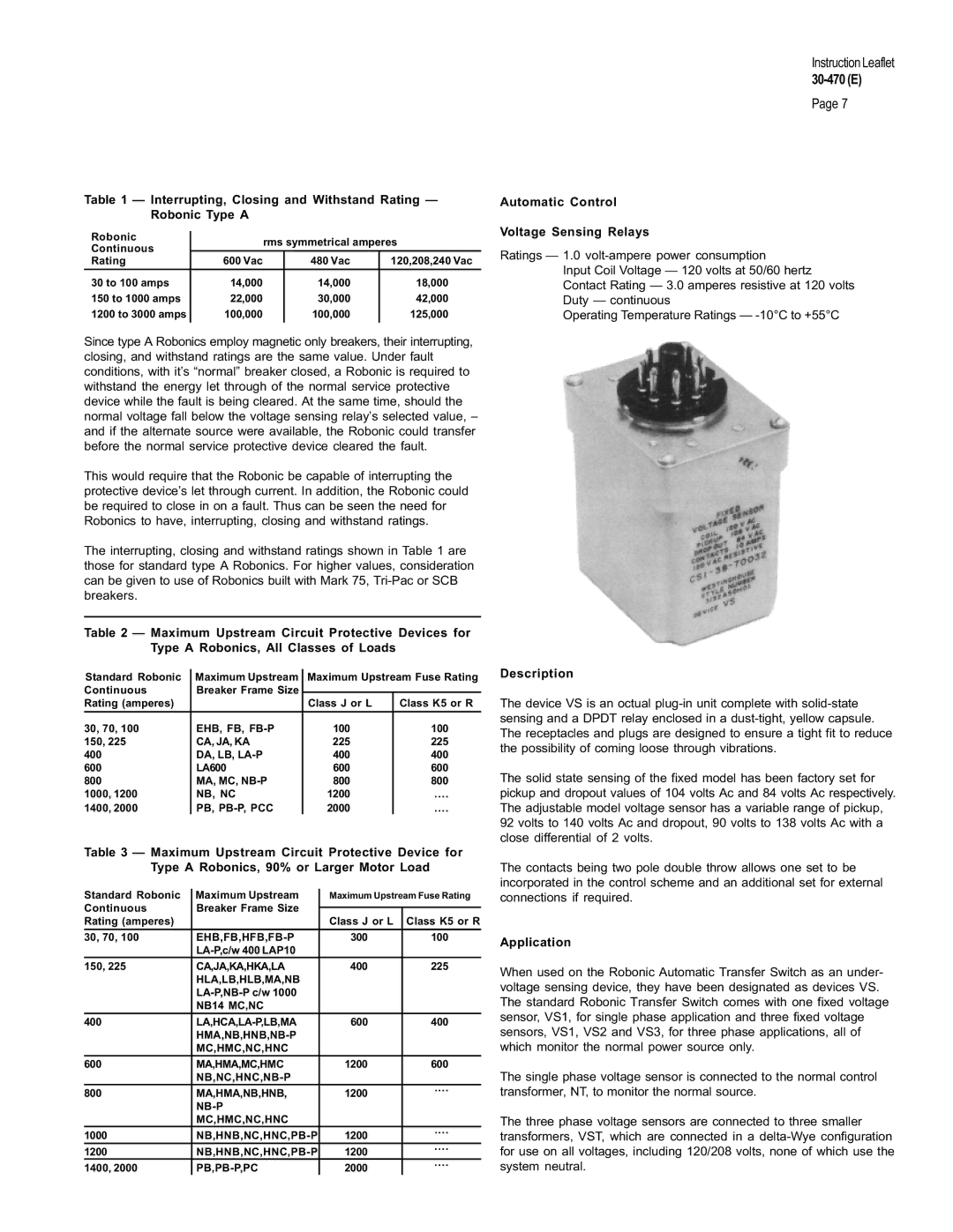
| The device VS is an octual | |
Rating (amperes) |
| Class J or L | Class K5 or R | ||
30, 70, 100 | EHB, FB, | 100 | 100 | sensing and a DPDT relay enclosed in a | |
The receptacles and plugs are designed to ensure a tight fit to reduce | |||||
150, 225 | CA, JA, KA | 225 | 225 | ||
the possibility of coming loose through vibrations. | |||||
400 | DA, LB, | 400 | 400 | ||
| |||||
600 | LA600 | 600 | 600 | The solid state sensing of the fixed model has been factory set for | |
800 | MA, MC, | 800 | 800 | ||
1000, 1200 | NB, NC | 1200 | .... | pickup and dropout values of 104 volts Ac and 84 volts Ac respectively. | |
1400, 2000 | PB, | 2000 | .... | The adjustable model voltage sensor has a variable range of pickup, | |
|
|
|
| 92 volts to 140 volts Ac and dropout, 90 volts to 138 volts Ac with a | |
|
|
|
| close differential of 2 volts. | |
Table 3 — Maximum Upstream Circuit Protective Device for Type A Robonics, 90% or Larger Motor Load
Standard Robonic | Maximum Upstream | Maximum Upstream Fuse Rating | |
Continuous | Breaker Frame Size |
|
|
|
| ||
Rating (amperes) |
| Class J or L | Class K5 or R |
|
|
|
|
30, 70, 100 | 300 | 100 | |
|
|
| |
150, 225 | CA,JA,KA,HKA,LA | 400 | 225 |
| HLA,LB,HLB,MA,NB |
|
|
|
|
| |
| NB14 MC,NC |
|
|
400 | 600 | 400 | |
|
|
| |
| MC,HMC,NC,HNC |
|
|
600 | MA,HMA,MC,HMC | 1200 | 600 |
|
|
| |
800 | MA,HMA,NB,HNB, | 1200 | .... |
| |||
|
|
| |
| MC,HMC,NC,HNC |
|
|
1000 | 1200 | .... | |
| |||
1200 | 1200 | .... | |
| |||
1400, 2000 | 2000 | .... | |
| |||
The contacts being two pole double throw allows one set to be incorporated in the control scheme and an additional set for external connections if required.
Application
When used on the Robonic Automatic Transfer Switch as an under- voltage sensing device, they have been designated as devices VS. The standard Robonic Transfer Switch comes with one fixed voltage sensor, VS1, for single phase application and three fixed voltage sensors, VS1, VS2 and VS3, for three phase applications, all of which monitor the normal power source only.
The single phase voltage sensor is connected to the normal control transformer, NT, to monitor the normal source.
The three phase voltage sensors are connected to three smaller transformers, VST, which are connected in a