Solid State Type

Ratings — 1.2 watts power consumption

Input Coil Voltage — 120 volts at 50/60 Hertz Contact Rating — 10 amperes resistive at 120 volts Time Range — 2 to 3 seconds — nonadjustable Operating Temperature Range — -10°C to +55°C

Description

Instruction Leaflet 30-470 (E)

Page 9

Control Relay (CR)

Ratings — 1.2 volt amperes power consumption

Input Coil Voltage — 120 volts 60 hertz and 50 hertz Contact Rating — 10 amperes resistive Operating Temperatures — -10°C to +55°C

Settings — 50 hertz fixed sensing or 60 hertz fixed sensing

Chart A

CONTROL RELAY CHARACTERISTICS pickup only

FrequencyPercent

Tolerance Levels

Percent Voltage

Description

This is an octal plug-in relay containing solid-state control, a Dc coil and a one pole single throw set of contacts complete in a dust-tight yellow capsule. The relay will pick up instantaneously when voltage is applied to the coil and remains in this position as long as the coil is energized. Timing begins immediately upon de-energization and at the end of the timing cycle, the contacts will return to their original position. If the power should return prior to the completion of the timing cycle, the relay will reset for another complete timing cycle.

Application

When used on the Robonic Automatic Transfer Switch as an engine starting relay, this relay has been designated as a device E.S. The relay is incorporated in the control scheme to delay the start-up of the engine-generator set until normal supply voltage has been interrupted for a longer time than the timing period. If normal supply voltage has not returned by the end of the delay period, the relay contacts cause the engine-generator set to start and when the emergency supply voltage and frequency has reached the pickup value of the control relay, the relay will energize and initiate the operation of the transfer switch to the emergency position.

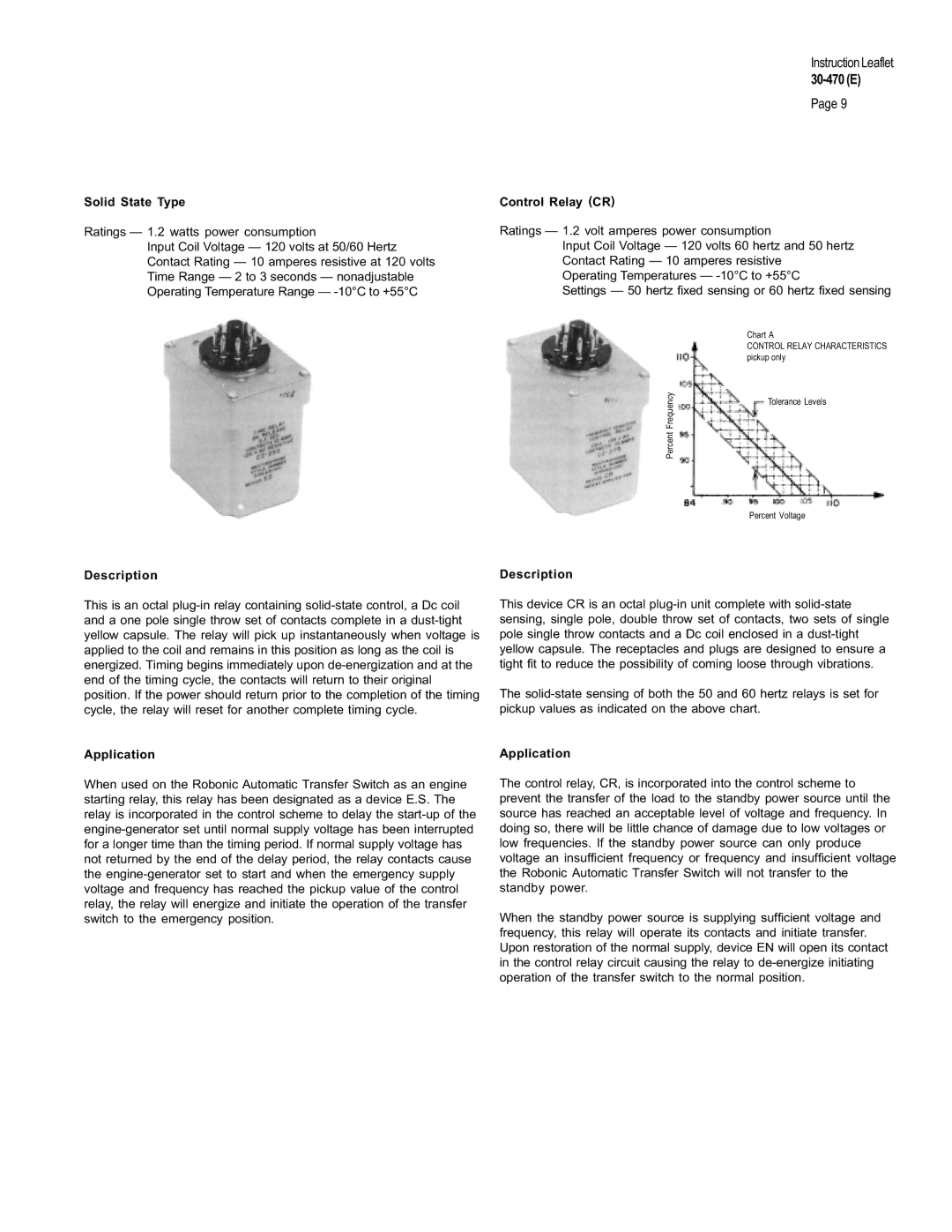
This device CR is an octal plug-in unit complete with solid-state sensing, single pole, double throw set of contacts, two sets of single pole single throw contacts and a Dc coil enclosed in a dust-tight yellow capsule. The receptacles and plugs are designed to ensure a tight fit to reduce the possibility of coming loose through vibrations.

The solid-state sensing of both the 50 and 60 hertz relays is set for pickup values as indicated on the above chart.

Application

The control relay, CR, is incorporated into the control scheme to prevent the transfer of the load to the standby power source until the source has reached an acceptable level of voltage and frequency. In doing so, there will be little chance of damage due to low voltages or low frequencies. If the standby power source can only produce voltage an insufficient frequency or frequency and insufficient voltage the Robonic Automatic Transfer Switch will not transfer to the standby power.

When the standby power source is supplying sufficient voltage and frequency, this relay will operate its contacts and initiate transfer. Upon restoration of the normal supply, device EN will open its contact in the control relay circuit causing the relay to de-energize initiating operation of the transfer switch to the normal position.
Page 9
Image 9
Westinghouse Switch warranty Chart a Control Relay Characteristics pickup only