Instruction Leaflet 30-470 (E)
Page 8
Automatic Control (Continued)
When adjustable type voltage sensors have been ordered, they are factory set to dropout at 90 volts and pickup at 108 volts Ac. For adjustment to other settings, first set the drop value and adjust the pickup to desired setting. This is done by using a variable power supply for the coil, pins 2 and 7, and using an ohm meter on the contacts to determine when the relay has
Additional relays are available for over voltage monitoring, emergency source monitoring, and 125 volt Dc applications.
Note: The pickup and dropout settings do vary with temperature variations at a rate of 0.1% per degree C from a nominal operating temperature of 25°C.
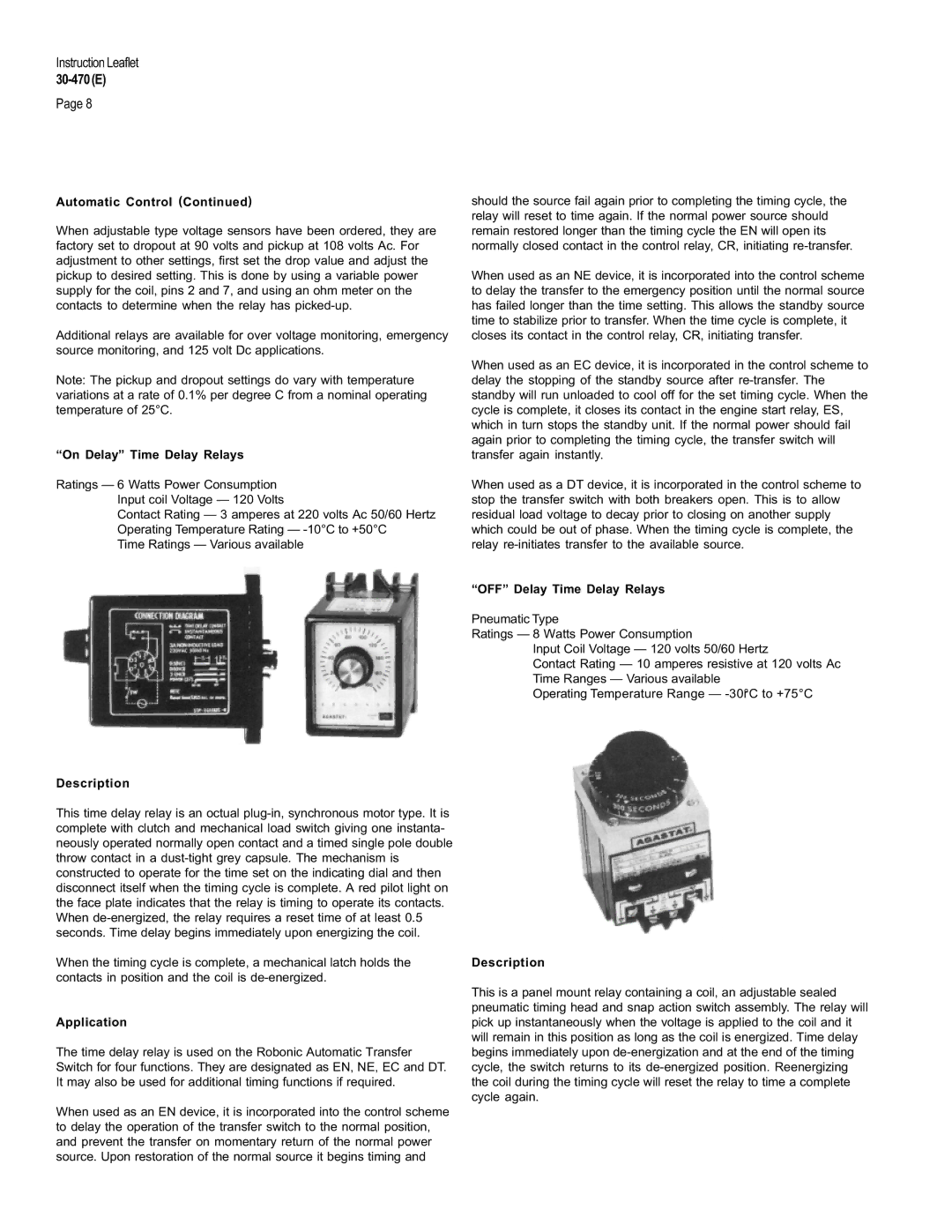
“On Delay” Time Delay Relays
Ratings — 6 Watts Power Consumption Input coil Voltage — 120 Volts
Contact Rating — 3 amperes at 220 volts Ac 50/60 Hertz Operating Temperature Rating —
Time Ratings — Various available
Description
This time delay relay is an octual
When the timing cycle is complete, a mechanical latch holds the contacts in position and the coil is
Application
The time delay relay is used on the Robonic Automatic Transfer Switch for four functions. They are designated as EN, NE, EC and DT. It may also be used for additional timing functions if required.
When used as an EN device, it is incorporated into the control scheme to delay the operation of the transfer switch to the normal position, and prevent the transfer on momentary return of the normal power source. Upon restoration of the normal source it begins timing and
should the source fail again prior to completing the timing cycle, the relay will reset to time again. If the normal power source should remain restored longer than the timing cycle the EN will open its normally closed contact in the control relay, CR, initiating
When used as an NE device, it is incorporated into the control scheme to delay the transfer to the emergency position until the normal source has failed longer than the time setting. This allows the standby source time to stabilize prior to transfer. When the time cycle is complete, it closes its contact in the control relay, CR, initiating transfer.
When used as an EC device, it is incorporated in the control scheme to delay the stopping of the standby source after
When used as a DT device, it is incorporated in the control scheme to stop the transfer switch with both breakers open. This is to allow residual load voltage to decay prior to closing on another supply which could be out of phase. When the timing cycle is complete, the relay
“OFF” Delay Time Delay Relays
Pneumatic Type
Ratings — 8 Watts Power Consumption
Input Coil Voltage — 120 volts 50/60 Hertz
Contact Rating — 10 amperes resistive at 120 volts Ac Time Ranges — Various available
Operating Temperature Range —
Description
This is a panel mount relay containing a coil, an adjustable sealed pneumatic timing head and snap action switch assembly. The relay will pick up instantaneously when the voltage is applied to the coil and it will remain in this position as long as the coil is energized. Time delay begins immediately upon