B.
Three-wire connection...
Where local codes permit |
| Where local codes permit |
connecting |
| connecting |
conductor to the neutral wire: |
| conductor to the neutral wire of the |
|
| power supply cable: |
|
|
|
WARNING |
| WARNING |
Exhaust requirements
![]() WARNING
WARNING
Fire Hazard
Use a heavy metal vent.
Do not use a plastic vent.
Do not use a metal foil vent.
Fire Hazard
Use a new UL approved 30 ampere power supply cord.
Use a UL approved strain relief.
Disconnect power before making electrical connections.
Connect neutral wire (white or center wire) to center terminal (silver).
Ground wire (green or bare wire) must be connected to green ground connector.
Connect remaining 2 supply wires to remaining 2 terminals (gold).
Securely tighten all electrical connections.
Failure to do so can result in death, fire, or electrical shock.
Fire Hazard
Use 10 gauge solid copper wire. Use a UL approved strain relief.
Disconnect power before making electrical connections.
Connect neutral wire (white or center wire) to center terminal (silver).
Ground wire (green or bare wire) must be connected to green ground connector.
Connect remaining 2 supply wires to remaining 2 terminals (gold).
Securely tighten all electrical connections.
Failure to do so can result in death, fire, or electrical shock.
Failure to do so can result in death or fire.
Important: Observe all governing codes and ordinances.
It is recommended that you exhaust your dryer to the outside for best performance. Moisture and lint indoors may cause:
•Lint to gather around the dryer where it can be fuel for a fire.
•Moisture damage to woodwork, furniture, paint, wallpaper, carpet, etc.
•Housecleaning problems and health problems.
If the washer/dryer is installed in a confined area such as a bedroom, bathroom or closet, it must be exhausted to the outside and provision must be made for enough air for
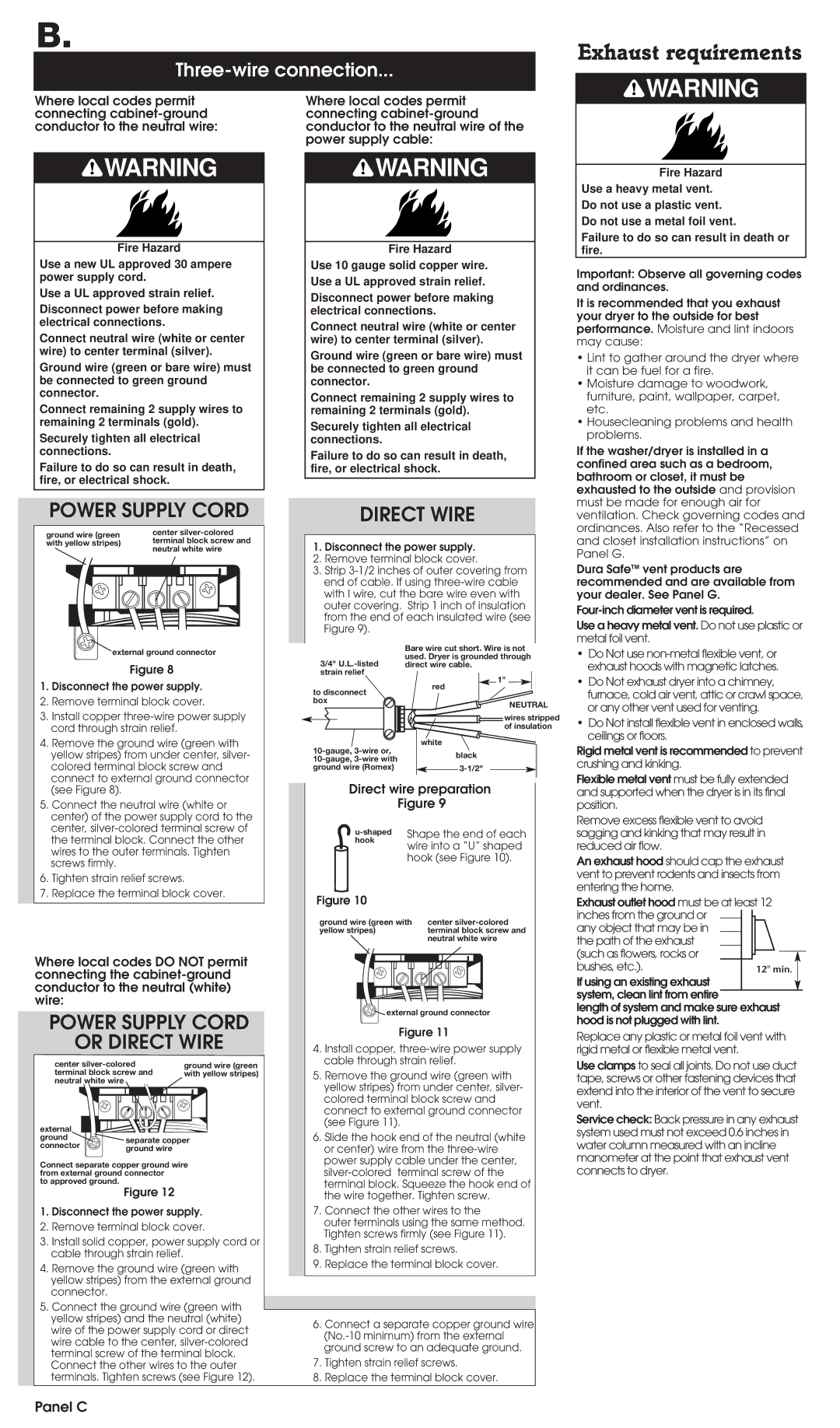
POWER SUPPLY CORD
ground wire (green |
|
|
|
| center | |||||||||||||
with yellow stripes) |
|
|
|
| terminal block screw and | |||||||||||||
|
|
|
|
|
|
|
|
|
| neutral white wire | ||||||||
|
|
|
|
|
|
|
|
|
|
|
|
|
|
|
|
|
|
|
|
|
|
|
|
|
|
|
|
|
|
|
|
|
|
|
|
|
|
|
|
|
|
|
|
|
|
|
|
|
|
|
|
|
|
|
|
|
|
|
|
|
|
|
|
|
|
|
|
|
|
|
|
|
|
|
|
|
|
|
|
|
|
|
|
|
|
|
|
|
|
|
|
|
|
|
|
|
|
|
|
|
|
|
|
|
|
|
|
|
|
|
|
|
|
|
|
|
|
|
|
|
|
|
|
|
|
|
|
|
|
|
|
|
|
|
|
|
|
|
|
|
|
|
|
|
|
|
|
|
|
|
|
external ground connector
Figure 8
1.Disconnect the power supply.
2.Remove terminal block cover.
3.Install copper
4.Remove the ground wire (green with yellow stripes) from under center, silver- colored terminal block screw and connect to external ground connector (see Figure 8).
5.Connect the neutral wire (white or center) of the power supply cord to the center,
6.Tighten strain relief screws.
7.Replace the terminal block cover.
Where local codes DO NOT permit connecting the
POWER SUPPLY CORD
OR DIRECT WIRE
center |
|
|
| ground wire (green | |||||||||
terminal block screw and |
|
|
| with yellow stripes) | |||||||||
neutral white wire |
|
|
|
|
|
|
|
|
|
|
| ||
|
|
|
|
|
|
| |||||||
|
|
|
|
|
|
|
|
|
|
|
|
|
|
|
|
|
|
|
|
|
|
|
|
|
|
|
|
|
|
|
|
|
|
|
|
|
|
|
|
|
|
|
|
|
|
|
|
|
|
|
|
|
|
|
|
|
|
|
|
|
|
|
|
|
|
|
|
|
|
|
|
|
|
|
|
|
|
|
|
|
|
|
|
|
|
|
|
|
|
|
|
|
|
|
|
|
|
external |
| |
ground | separate copper | |
connector | ||
ground wire | ||
|
Connect separate copper ground wire from external ground connector
to approved ground.
Figure 12
1.Disconnect the power supply.
2.Remove terminal block cover.
3.Install solid copper, power supply cord or cable through strain relief.
4.Remove the ground wire (green with yellow stripes) from the external ground connector.
5.Connect the ground wire (green with yellow stripes) and the neutral (white) wire of the power supply cord or direct wire cable to the center,
DIRECT WIRE
1.Disconnect the power supply.
2.Remove terminal block cover.
3.Strip
Bare wire cut short. Wire is not used. Dryer is grounded through
3/4"
| 1" | |
to disconnect | red | |
| ||
box | NEUTRAL | |
| ||
| wires stripped | |
| of insulation | |
white | ||
black | ||
| ||
ground wire (Romex) |
Direct wire preparation
| Figure 9 |
Shape the end of each | |
hook | wire into a “U” shaped |
| |
| hook (see Figure 10). |
Figure 10
ground wire (green with |
| center | |||||||||||
yellow stripes) |
| terminal block screw and | |||||||||||
|
|
|
|
|
|
| neutral white wire | ||||||
|
|
|
|
|
|
|
|
|
|
|
|
|
|
|
|
|
|
|
|
|
|
|
|
|
|
|
|
|
|
|
|
|
|
|
|
|
|
|
|
|
|
|
|
|
|
|
|
|
|
|
|
|
|
|
|
|
|
|
|
|
|
|
|
|
|
|
|
|
|
|
|
|
|
|
|
|
|
|
|
|
|
|
|
|
|
|
|
|
|
|
|
|
|
|
|
|
|
external ground connector
Figure 11
4.Install copper,
5.Remove the ground wire (green with yellow stripes) from under center, silver- colored terminal block screw and connect to external ground connector (see Figure 11).
6.Slide the hook end of the neutral (white or center) wire from the
7.Connect the other wires to the
outer terminals using the same method. Tighten screws firmly (see Figure 11).
8.Tighten strain relief screws.
9.Replace the terminal block cover.
6.Connect a separate copper ground wire
7.Tighten strain relief screws.
8.Replace the terminal block cover.
ventilation. Check governing codes and ordinances. Also refer to the “Recessed and closet installation instructions” on Panel G.
Dura SafeTM vent products are recommended and are available from your dealer. See Panel G.
Use a heavy metal vent. Do not use plastic or metal foil vent.
•Do Not use
•Do Not exhaust dryer into a chimney, furnace, cold air vent, attic or crawl space, or any other vent used for venting.
•Do Not install flexible vent in enclosed walls, ceilings or floors.
Rigid metal vent is recommended to prevent crushing and kinking.
Flexible metal vent must be fully extended and supported when the dryer is in its final position.
Remove excess flexible vent to avoid sagging and kinking that may result in reduced air flow.
An exhaust hood should cap the exhaust vent to prevent rodents and insects from entering the home.
Exhaust outlet hood must be at least 12 inches from the ground or ![]()
![]() any object that may be in
any object that may be in
the path of the exhaust (such as flowers, rocks or bushes, etc.).
If using an existing exhaust system, clean lint from entire
length of system and make sure exhaust hood is not plugged with lint.
Replace any plastic or metal foil vent with rigid metal or flexible metal vent.
Use clamps to seal all joints. Do not use duct tape, screws or other fastening devices that extend into the interior of the vent to secure vent.
Service check: Back pressure in any exhaust system used must not exceed 0.6 inches in water column measured with an incline manometer at the point that exhaust vent connects to dryer.