For use where local codes permit use of flexible power supply cord.
Figure 3 | Figure 4 |
A.
Four-wire connection...
![]() WARNING
WARNING![]() WARNING
WARNING
Direct wire
Fire Hazard
Use a new UL approved 30 ampere power supply cord.
Use a UL approved strain relief.
Disconnect power before making electrical connections.
Connect neutral wire (white or center wire) to center terminal (silver).
Ground wire (green or bare wire) must be connected to green ground connector.
Connect remaining 2 supply wires to remaining 2 terminals (gold).
Securely tighten all electrical connections.
Failure to do so can result in death, fire, or electrical shock.
Fire Hazard
Use 10 gauge solid copper wire. Use a UL approved strain relief.
Disconnect power before making electrical connections.
Connect neutral wire (white or center wire) to center terminal (silver).
Ground wire (green or bare wire) must be connected to green ground connector.
Connect remaining 2 supply wires to remaining 2 terminals (gold).
Securely tighten all electrical connections.
Failure to do so can result in death, fire, or electrical shock.
The washer/dryer can be connected directly to fused disconnect or circuit breaker box with
A conduit connector must be installed at junction box. USE ONLY
Electrical connection
This dryer is manufactured with the
GROUND INSTRUCTIONS: This appliance must be grounded. In the event of malfunction or breakdown, ground will reduce the risk of electric shock by providing a path of least resistance for electric current.
If using a power supply cord, the plug must be plugged into an appropriate outlet that is properly installed and grounded in accordance with all local codes and ordinances.
If using a direct wire connection, this appliance must be connected to a grounded metal, permanent wiring system; or an
WARNING - Improper connection of the
If the house has aluminum wiring, follow the procedure below:
a)Connect a section of 8 gauge solid copper wire to the connector block.
b)Connect the aluminum wiring to the added section of copper wire using special connectors designed and Underwriters Laboratories Listed for joining copper to aluminum. Follow the electrical connector manufacturer's recommended procedure.
c)Aluminum/copper connection must conform with local codes and industry accepted wiring practices.
POWER SUPPLY CORD
center silver- |
|
|
| ground wire (green | ||||||||||||||
colored terminal |
|
|
| with yellow stripes) | ||||||||||||||
block screw and |
|
|
|
|
|
|
|
|
| |||||||||
neutral white wire |
|
|
|
|
|
|
|
|
| |||||||||
|
|
|
|
|
|
|
|
|
|
|
|
|
|
|
|
|
|
|
|
|
|
|
|
|
|
|
|
|
|
|
|
|
|
|
|
|
|
|
|
|
|
|
|
|
|
|
|
|
|
|
|
|
|
|
|
|
|
|
|
|
|
|
|
|
|
|
|
|
|
|
|
|
|
|
|
|
|
|
|
|
|
|
|
|
|
|
|
|
|
|
|
|
|
|
|
|
|
|
|
|
|
|
|
|
|
|
|
|
|
|
|
|
|
|
|
|
|
|
|
|
|
|
|
|
|
|
|
|
|
|
|
|
power supply cord ground wire (green)
external ground connector
Figure 5
1.Disconnect the power supply.
2.Remove terminal block cover.
3.Install copper,
4.Remove the ground wire (green with yellow stripes) from the external ground connector and fasten under center,
5.Connect the ground wire (green) of the copper,
6.Connect the neutral wire (white) of the power supply cord to the center,
7.Tighten strain relief screws.
8.Replace the terminal block cover.
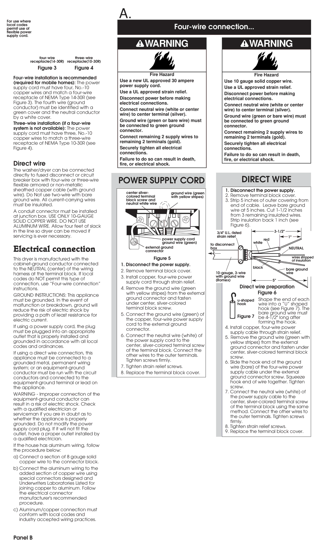
DIRECT WIRE
1.Disconnect the power supply.
2.Remove terminal block cover.
3.Strip 5 inches of outer covering from end of cable. Leave bare ground wire at 5 inches. Cut
3/4" |
| |
strain relief |
| 1" |
| white | red |
to disconnect |
| |
|
| |
box |
| NEUTRAL |
|
| wires stripped |
|
| of insulation |
| black | bare ground |
| ||
| wire | |
with ground wire |
|
|
(Romex) |
| 5" |
Direct wire preparation
Figure 6
Shape the end of each | |
hook | wire into a “U” shaped |
| hook (see Figure 7). The |
Figure 7 | bare ground wire must |
be | |
| forming the hook. |
4.Install copper,
5.Remove the ground wire (green with yellow stripes) from the external ground connector and fasten under center,
6.Slide the hook end of the ground wire (bare) of the
7.Connect the neutral wire (white) of the power supply cable to the center,
8.Tighten strain relief screws.
9.Replace the terminal block cover.