Water requirements
The cold water line to the ice maker requires
tubing.
A threaded compression fitting to
connect the water line to the inlet valve is I” the parts bag
Install a
Drain requirements
This appliance is equipped with a gravity drain and a 4’.long.
5/a’- 0.D rubber, drain tube
Recommended method
Install a
standplpe directly below the drain tube outlet. (See Panel A for
dimensions )
It may be desirable to Insulate the drain line up to the drain inlet to
minimize condensation on the drain tube
Alternate method
Ii a drain connection directly below the drain tube outlet Is not available.
a drain |
| pump | (Part No | EKDPB) | WIII | ||
need | to | be | installed. | The | drain |
| |
pump, |
| available | from | your | local |
| |
authorized | parts | distributor. | lifts | water | |||
to an | avaIlable |
| drain. |
|
|
| |
Electrical Shock Hazard
Disconnect power supply.
Failure to do so could result in electrical shock or personal injury.
1.Follow steps 1 through 10 of the Snow start .” section
2.Install the drain oumo on the floor near the center of the rear
wall |
| of | the | cabinet | opening. |
| The |
| |||
side | of | drain | pump | with | the |
|
|
| |||
discharge |
| tube | should |
| face | the | rear | ||||
of | the |
| obenlng |
|
|
|
|
|
|
| |
3 | Remove | the | rubber |
| drain | hose |
| ||||
and | connect | the | bin | drain | directly | to | |||||
the | pump | using | 5/B” | I D. plastic | hose. | ||||||
(See | Figure | 4.) |
|
|
|
|
|
|
| ||
4 | Run | pump | drain | hose | to | drain |
| ||||
(See | Figure | 4.) |
|
|
|
|
|
|
| ||
5 | Run | the | power |
| supply | cord | from | ||||
the | puma | throuah | the | hole | I” | the |
| ||||
rear’of |
| the | ice | Gaker. |
| (See | Figure | 4.) | |||
YFigure 4
6 Remove the two screws attaching the afr grille to the ice maker.
Remove the air grille (See Figure 5 )
|
|
| Figure | 5 |
|
|
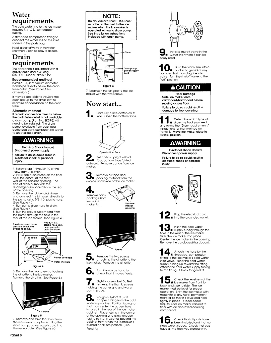
7 Remove | and save | the shunt | from | |||
the | ice maker | receptacle | Plug | the | ||
drain | pump, |
| power | supply | cord | into |
the | receptacle. |
| (See Figure | 6.) |
| |
NOTE:
Do Not discard shunt. The shunt must be reattached to the ice maker when the Ice maker is operated without a drain pump. See Installation Instructions included with drain pump.
Figure 6
7.Reattach the air grille to the Ice maker with the two screws
Now start...
1 |
| Carefully | place | carton | on Its |
| H | side. Open | the | bottom | flaps |
CD
open twnom 1lOPl
2 Set carton upright with all
H four. bottom flaps folded
outward. Remove carton from Ice maker.
3 n | Remove | all | tape | and |
| |
packing |
| material | from | the | ||
outside | and | InsIde | of the | ice | maker | |
4.
Remove parts
package from Inside Ice maker bin
|
| Remove |
| the | two | screws |
| |||||
5 | W | attaching |
|
| the |
| air | grille | to | the | ||
Ice | maker. | Remove |
| the | air | grille. |
| |||||
6 n | Turn | the | fan |
| by | hand |
| to |
| |||
check | that | It | moves |
| freely |
| ||||||
7n | Slightly | loosen, |
| but | Do Not | |||||||
remove, |
| the | thumb |
| screws | |||||||
holding | the | cutter |
| grid | and | water |
| |||||
pan | in | place |
|
|
|
|
|
|
|
|
|
|
8 n | Rough | in |
|
| soft |
| ||||||
copper | tubing |
| from | the | cold | |||||||
water | supply |
| line |
| PosItion |
| tubing | so | ||||
that | It can | enter | the | access |
| hole |
| |||||
located | I” | the | rear | of | the | ice | maker | |||||
cabinet | Place |
| tubing |
| in | the | center | |||||
of | the | opening | and | allow | enough |
| ||||||
tubing | so that | It | extends |
| beyond | the | ||||||
cablnet | front | when | the | icemaker | is | |||||||
pushed | back | Into | position |
| [See |
| ||||||
Panel | A), |
|
|
|
|
|
|
|
|
|
| |
9 n | Install | a shutoff | valve | I” the |
water | line where | It can | be | |
easily | used |
|
|
|
10 Flush the water line into a n bucket to get rid of any
particles that may clog the Inlet
valve. Turn the shutoff valve to the “off” posltion.
Failure to do so could result in
11 Determine which type of
n drain method you need and follow the *Drain requirements”
Instructions for that method on Panel B. Move Ice maker close to Its final position.
Electrical Shock Hazard
Disconnect power supply.
Failure to do so could result in electrical shock or personal
12 Plug the electrical cord
1 Into the grounded outlet.
13 Insert the
n suoolv tublna through the hole in the r&r bf the i:e maker Slide the ice maker Into place.
Center the Ice maker I” the opening. Remove the cardboard/hardboard
14 Attach the hose by the
n threaded. compreSSlon fitting to the ice makers
inlet valve. Bend the
supply tubing up toward the flttlng.
Attach the
to the fitting Check for good fit
15 n | Check |
| the | levelness | of | the | |||||
ice | maker | from | front | to |
| ||||||
back | and | side | to | side | The | ice |
|
| |||
maker | must | be |
| level | for | proper |
|
| |||
operation. |
| Shim | the | ice | maker | with | |||||
masonlte | or | any | hard, | permanent |
|
| |||||
material | so | that |
| It | is level | and | held |
| |||
tightly | I” | place |
| If | local | codes |
|
| |||
require. | seal | Ice | maker | cabinet | to | ||||||
floor | with | an | approved | caulking |
|
| |||||
compound |
|
|
|
|
|
|
|
|
|
| |
16 n | Check |
| that | all | parts | have | |||||
been |
| installed | and | that | no | ||||||
steps | were | skipped. |
| Check | that | you | |||||
have | all the | tools |
| you | started | with. |
| ||||