10 towerlevelinglegs
. “pfxoxlrwtelv l/d‘ Move range close to Rnal positron Remove the
cardboard or hardboard from under the range Plug power supply cord into the grounded outlet
|
| Cartzfully | move | range | to | flnol | ||||
| . | post,“” | Remove | brorler | or look | |||||
underneath |
| the | range |
| (a | flashlight | mov | |||
be | needed). |
| Check | that | the | re0r | levellw | |||
leg | In engaged |
| In the | bracket | ||||||
(For | nocabinet |
| instollatrons. | check | that | |||||
both | re0r | legs | ore engaged | in | ||||||
brackets.) |
| If0 | leveling |
| leg | Is not propertv | ||||
engaged. |
| rermve | and | reposition | me | |||||
bracket | to | insure | ttat | the | leveling | IeQ fits | ||||
propertv | In | the | bracket |
|
|
|
|
| ||
12.If ~“sloll~ng the rn”Qe I” 0 rwb~le h~me.v”“M”STsec”reth;
range lo the floor Any method of seC”rl”~ the rorwe IS“deauote “s iorx
0s It c”“t”rms
13 Place
. Place Id side to side
to back If the range ISnot
level. pull the range forward until rear leveling leg Is removed from the bracket. Adjust the legs up or down until range IS level. Push range bock Into
positron. Check that WE ,eQl kVeli~ IeQ is enQ”Qed
bracket. Replace the StO‘OQedrawer
01 broiler drawer.
Note: Oven must be level
sOMOCt”ly b0ktnQ condlti
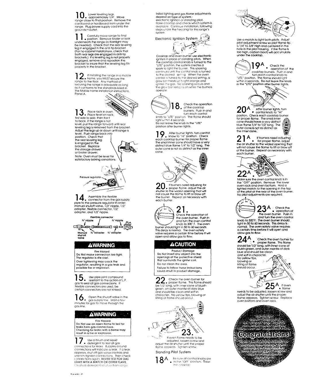
14 Assemble the Rexlble
. connector from the Qas supply pipe to the pressure regulator in order. rnonual shutoff valve, 112’ nipple, 112’
adapter. flexible connector. 112’ adapter. and 112’ nipple.
1 5 |
| UT pipe | joint | compound |
|
| . | resistant | to the actron | of L P | |
gas to | se0 | “II gas | c”““ec+,“ns. | If | |
flexible | connectors | ore | used. be |
| |
Certoln | connectors | ore | not klnked |
| |
16Open the shu:ol: votve rn the
-go5 suppiy he wart 0 rev, minutes for gas to move through Ihe QOS Ilne.
17 Use 0 brush “RC Ilqurd
. detergent to test “IIgos ~onne~l~ons for leaks Bubbles “round c”“nect,“ns will lndlcoie 0 leak I: 0 leak oppeors. shut off Qas ““ive controls and
wwnch~hghten connec:~ons Then check ~Onr~e~tlor~s ogolrl NEVER TEST FOR GAS LEAKS WITH A MATCH OR OTHER FLAME.
lnilial lighllng and gar flame odjustmenfs depend on type of ryrfem
electronic ignillon or standlng pllot.
Raw cocktop ond check whch sptem IS “vo~lable Conl~nue ~nstollahon. following SkpS under me heodlng for th,s range’s
system-
Cookfop and ““en burner “se ele&o”fC roniters in “lace of stondirx ~lois When t& ccmktbp control knob 5 turned to the ‘LITE- posItIon. the system creofes 0 spark to light the burner This spaking conhn~es unhl tae control knob ISturned
lo lhe dewed se?g When the 0”e” c”“,,“, IS twned to !he desired ZtiI”Q. 0 glow bt: he0ts u? bright orange and igmtes ;?e gas NC szorklng occurs and the Qlcr; 30’ remc % on while the burners operok?
Check the operatl””
1 8. ofthecooktop
burners Push in ond turn each control
knob to
Do ml leave Ihe Crab in Ihe “LITE” posrtron after burner lights.
19 AHer burner lights. turn control know to ‘HI’ position. Check
Wch c’ooktop burner for proper flame.
The
If burners need “dfusting for l proper flame. adjust the ok shutter to the w,dest opening that vlll
not cause the flame to lift or blow ofl the burner Repeat 0s necessary witi Wch burner
n”
2 1
Check t;le operation of me oven burner. Push I” and turn the oven c0i7h”l knob to 3CQ’ F. The “Yen
burner should llaht in 50 to 60 seconds.
Thk delay ISno& The 0”en safety valve requires 0 certain time before It till “pen and oflow gas to Row.
Do Not insert any object into the openings of the protective shield
that surrounds | the | tqniler | coil. |
|
1 Donolcleanlheor~o. |
|
|
| 1 |
Failure to follow these inrtructrons |
| |||
could result in product | damage. |
| ||
Check | the | ““en burner | for | |
22 . proper | flame. | This Rome | should | |
be l/2’ long. wth !nner cone of bluish
green. | on | outer | mcnl,e | of | dark | blue |
|
and | should | tx | &on | and | soft | in |
|
character. | No | vel;ow | tips, | blowing | or | ||
lllt,ng | of flame | s,culd | occur |
|
|
| |
It oven flame needs I” be odyxted. loose” screw and
od,ust I%? “11shu7er until the proper
flame copeors ii,lhlen screw
Standing Pilot Syslem
18* Ee su.0 “11c”“:r”, knobs are
. in i+
Use 0 match to liaht both 0llots. Adivst pilot adjustment screw so bllot Ram& tip Is l/4’ to 318’ hkrh and centered in the
hole In the plfo<housing. If the name Is
to0 high.carbon (soot) wnl
cooktop burners. Push ,n and turn each control knob to
‘LITE’ poslHon. The flame should I,Qht within 4 seconds. Do not leove the knob in the “LITE” poslllon titer burner lights.
|
|
| After | buner | HQhk. | turn | |
|
| l | control | knob | to ‘HI- | ||
position. | check | each cooktop | burner | ||||
for proper t%xne. The smafl inner |
| ||||||
c0ne | should | have | a | very distinct | fl | ||
blue | flame | 1/4’to’1/2’tong. | The | [ | |||
outer | co- | knot | as | dffHnct | 0s |
| |
the | inner | cone: |
|
|
| il | |
21A If tuners need adjusting-
. for proper name.adjust the air shuiter to the widest opening tit
will not cow the Rome to Ilfi or blow off of fhe bwner. Repeat OS necess0rv wlth
Make sure the ““en control knob Is In the
No PIlot “djustmenk ore required
.
23A.g::h&
the 0ven burner. Push In
kn0btoJo’F. ~0~enb~rnerSh0ulc.
light In 50 t&CO seconds. MS de@ Is narrml. The oven safety valve Pequlres 0 certain
“nowQasto rlow
24A.
proper nap. Thti Rome should be l/2’ long. with lnrw cone of
blukhgr&n. and tier tonne of do* blue~3rds0nand should be clean
In ctwrocter.
sMuld occur.
needs to be adjusted. loosen screw and adjust the air shutter until the proper flame appears. Tighten zcrew Replace ““en bottom and oven rack.