Electrical
Requirements
(II model is sa equipped.)
Eleclrical Shock Hazard
*Eleclricol gwund is requwd on this appliance.
. Improper |
| connection | of | the |
|
| |||
equipment | grounding | conductor |
| ||||||
CO” | WS”ll | 111he. | ele~,r,cd | shock, |
| ||||
or other pe sono, ,n,ury. |
|
|
| ||||||
* Check | w~lh o | quaIllied | eleclr~clan | ir | |||||
you | are | I” doubl | os lo whelher | Ihe |
| ||||
“PDlionce | IS PrOPerI” | orounded. |
| Do | |||||
No1 | mod,fy | Ihe | p&r;u,~ply |
| cotd |
| |||
plug | If II | will | not ht Ihe | outlet, | hove |
| |||
o proper |
| outlet |
| inslalled |
| by o |
|
| |
qualified |
| electrician. |
|
|
|
| |||
. Do | Nol | “se and | extension | cord wlh | |||||
this | appliance. |
|
|
|
|
|
| ||
*Do Not have o fuse in Ihe neutrot or
groundlng 5rcuII. A fuse in the neulrol or grounding circuit could
Electwol |
| ground | Is rcqu~rod | on | thin |
| ||||
appllarlcc |
|
|
|
|
|
|
|
|
| |
II chan~u,g | ar,d | proper,y | yrourxl~ny | Ihe | ||||||
wall | rcceplocle |
| IS~rn~mss~bio | and | where | |||||
loco, c?dos pcrm,, (consul! you, |
| 5. | ||||||||
elechlc | aI | ~nspeclor). | o | temporary |
| |||||
adaptor | may | ~XZplugged | [“IO the |
| ||||||
exlstlw |
| wall | receplocle |
| to | mote | ||||
wlrn | powi | SUPPIYcord | of INS | |||||||
is done. | you mu4 | connect | o |
|
|
| ||||
se~orole |
| CODDW | wound\“4 | wire | (No.10 | |||||
minimum) |
| too | gr&nded | cold water | ||||||
pipe b’/ means of o clomp and then lo | ||||||||||
me exlerno | groundtng | cO”“eclor |
| screw | ||||||
Do not ground lo o gas supply pipe or | ||||||||||
hot | waler |
| IXLX |
| Do | not | connect | to |
| |
resull in an electrical shock. Failure lo fo11su these inslruclions could resull in Ilre, electrical shock or olher persz~nal injury.
I |
|
| i |
A | 120Volt. | 154mpere | |
md | electrlcc~l supptv | ls required | |
elechkipn | to see If i1 Is co&$ | wired. |
,‘$ | I:‘ >- |
|
A tiring dia$an) k lrr&dedJtilit~r&x
package. llw wiring diagram k also located on th+ bock of the range.
Recokmtitidkd Grounding Methc d
Do NOT. UNDER ANY CIRCUMSTANCES.
REMOVE THE POWER SUPPLY CORD.
GROyJDlNG;FRONG.
For your per&wlsafe&;thls | a;jdlt&e |
Figure 1 “I’
Temporary
Grounding Methc bd
DO NOT, UNDER ANY CIRCUMSTANCES, REMOVE THE POWER SUPPLY CORD GROUNDING ‘RONG.
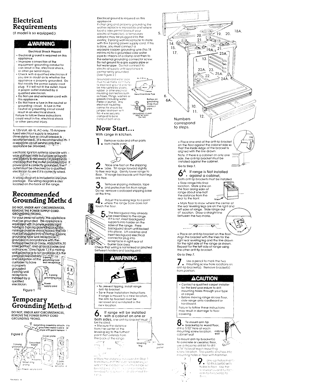
Now Start...
Wilh range in kitchen.
1 llemove racks ond other oarts
1 l tromlrwdeoven
2, ‘10ce one foot on the shipplng
. 30% IIt range forward slightly t0 free rear legs Gentiy lower rO”Qe to floor. Tlt range bockwords until front legs are hee
3 . | &move | shippIng |
| motenols. | lope | |
2nd protechve | 11lm horn range | |||||
Do | no | remove | cardboard | shipping | base | |
ot | this | hme |
|
|
|
|
4 Ad ust the leve,,ng IeQs to Q point
. d/herei the range base does not touch be floor
The backguard may olreadv
. be assembled to the range lf It is not. insert bockguord supports into holder on the sides of the ronoe. Press
; backguord do& until locked into place. Lift cooktop and
insert buckguard electrical
:connector plug Into
receptacle in right rear of
. bwrw box are”
Check nMt wiring is not klnked or pinched
bebeen holders and backguard.
*To Iprevent Ilpping, lnslall range
. Saw these Inslollol,on lnslruclions If rtlnge IS moved 10 o new locol,on, the
6 If,range will be installed
. wtlh a cabinet on one or bath sides, one
correspond to steps.
. Place one end of he
Nofe, If there ISo cabinet on only one side. the
Go lo Slep 7.
6A If range is Not installed - against a cabinet,
both
-Slide range Into rlnai
lkcat~on Mati a line on the floor ‘3lOnQ sides of ron~e about
the distance from the
rear to me front | II |
. Mock floor to show where the center of ihe rear leveling legs ore on the right ond lett s,des of range Slide range out
of location. Draw o straight l~ne between the two marks.
. Place on anti% bracket on the Align the brockei with the lines for the right rear k?Voli”Q leg one the line drown for the rlQht side of the ro”Qe OS show”. Reped for the let+ side of rang‘2 using the other
Go lo Step 7.
7 Use 0 pencil lo mark the two
. mounting screw hole locations on
on:%tlp bracket(s) Remove brockel(s) from poslt~on.
. Conlocl a quaIlfled carpet ,ns,aller
for Ihe besl procedure lo drill mounting holes lhrough your tvpe of corpe1.
*Before moving range across floor,
slide range onlo cardboard or hardboard
Fo~lure lo lollow lhere ~nslruclions may rerull in damage lo rioor CoverIng.