E IF CONNECTING TO A 4-WIFtE
. ELECTRICAL SYSTEM:This appliance is msnufactured with ground connected to cabinet. The ground must be revised so the green grounding wire of the
When a
The IvXWMUM conductor sizes for
the copper
2.
1,
F The wiring diagram L also
. located on the back of the range.
Now start...
With range in kitchen. Removeracksand other parts from
1. inside oven
2.
Place one foot on the shi~~ina base. Tilt range forward slightly
backwards until front legs ere free.
3 Remove shipping materiels,
. tape and protective film from range. Do not remove cardboard shipping base at tbis the.
4 Adjust the levehng legs
. approximately l/4’ or to a point where the range base does not touch the iloor. (If model is so equipped.)
Persona3lniurv Hazard
Carefully remove
Faflure to follow this hast.rnction may result in personal injury.
J
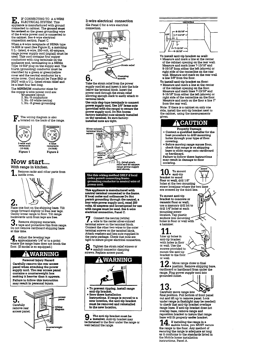
3-wire electrical connection
SeePanel C for
connection
Take the strsjn relief from the power supplycordkitandfnsertitintothehole
MOWtbteIUlblblock.hlSertthe
power cord through the snalu relief allowinuenouahslacktoeasfivattachto tetminr;ihlook-
Use only
sil”, tern nu*
ef md
This appllauca Is mauufachxed with neutIal tmlninal wnuected to the frame. If local ocdw and ordinancw Do Not pmmit grounding through the neutral. a
7 Connect the neunal (white)
. wire to the center
8 Tighten the stmin relief screws or mconduit connector clamping
screws. Replaze eccesspanel
a To prevent tipping, install range
n Save thew hatallation
Instrwtlons. | If range | in moved | to | a |
new locatlos the
In the new location.
ill0
9. installed.
-
To Install
of the cabinet opening o* the rear wall. Measure end mark lines
To InstaIl anti-tip bracket on flooc
lMeasure and mark a line at the center of the cabinet opening on the Soor. Measure and mark lines
Note: If there is a cabinet on only one side, install the
| Propeay | Damage |
|
1 Contact a qualified insteller for the | |||
best procedure to drill mounting |
| ||
holes through your type of floor |
| ||
covering. |
|
| |
1 Before moving range across floor, |
| ||
check that range is on shipping |
| ||
base or slide renae onto cardboard |
| ||
orhardboard. | - |
| |
Failure to follow these instructions |
| ||
may result in damage to floor |
| ||
covering. |
|
| |
bracket | to wood |
|
|
floor or wall, driJl l/3’ |
|
| |
holes at the two motmtmg |
| ||
screw locations where the two bnes | ,, | ||
ere crossed by the third line. | |||
To mount |
|
| |
bracket | to concrete or |
| |
ceradc | floor or wall, |
|
|
use a masonry drill bit to |
| ||
ddl l/4’ holes at each |
| ||
mounting screw |
|
| |
location | Tap plastic |
|
|
anchors km mounting holes in floor or wall with a hammer,
11.
Line up holes in
Move range close to fineI |
| |
12n position. Remove shipping base, | ||
cardboard or herdboard horn under the | ||
range. Plug power supply cord into | ||
grounded outlet. | I II | I Ill |
| ||
13.
Carefully move range
final position Pull bottom of front panel out and lift up to remove penel. Look under range (a Saahlight may be needed) to check that
the range to the floor.‘Any method of securing the range is ad&ate as long as it conforms to the stauderds l&ted io the Mobile home installation instructions, Panel A.