Gas supply requirements
Observe all governing codes and ordinances
Fire Hazard
l Range must be connected to a regulated gas supply.
lL.P.gas supply must Not exceed a pressure of 14” water column. Thls must be checked by a qualttled technlclan betore lnstalllng the range.
lDo Not use an open tlame to test tar
leaks trom gas connectlons.
l New, A.G.A. cleslgn-certltled, tlexlble gas line should be used when codes permit.
Failure to tallow these lnstructlons could 1 result In a We, explosion or personal Injury.
A n This installation must conform with
local codes and ordinances. In the absence of local codes, installations must conform with American National Standard, National Fuel Gas Code ANSI 2223.1 - latest edition.”
B w Input ratings shown on the serial/rating plate are for elevations up to 2,000 feet. For elevations above 2,000 feet, ratings are reduced at a rate of 4% for each 1,000 feet above sea level.
C w This range is design-certified by A.G.A. for NATURAL and L.P. gases with
appropriate conversion. The serial/rating plate located under the cooktop has information for the type of gas that can be used. If this information does not agree with the type of gas available, check with the local gas supplier. See Panel C and back cover for gas conversion instructions,
D W Provide a gas supply line of 3/4” rigid pipe to the range location, A smaller stze pipe on long runs may result in insufficient gas supply. Pipe-joint compounds made for use with L.P. gas must be used. With L.P. gas, piping or tubing size can be l/2” minimum. L.P. gas suppliers usually determine the size and materlals used on the system.
EW If local codes permit, a
new A.G.A.design-certified, 4 - 5 foot long,1 /2” or 3/4” I.D., flexible metal
appliance connector is recommended for connecting this range to the gas supply line. Do Not kink or damage the flexible tubing when moving the range. A l/2-inch male pipe thread is needed for connection to pressure regulator female pipe threads.
Fn | | toqg-- | |
The | shall | be | -~i;c | | PlY |
supply | line | p | | |
equipped | with | an approved | shutoff | valve. |
This valve | should | be | located | in the | same |
room as the range and should be in a location that allows ease of opening and closing. Do Not block access to shutoff valve.
Glw If rigid pipe is used
line, a combination of pipe used to obtain an in-line co
range. All strains must be removed from the supply and fuel lines so range will be level and in line.
H n The inlet pressure must be a minimum of 1 inch’above the set pressure of the regulator, a maximum of 14 inches total inlet pressure.
Set Pressure:
Natural Gas 4 Inches
L.P.Gas 10 Inches
I W Llne pressure testlng:
Testing above l/2 psl (gauge)
The range and its individual shutoff valve
must be disconnected from the gas supply piping system during any pressure testing of that system at test pressures greater than l/2 psig (3.5 kPa).
Testing at l/2 psi (gauge)
The range must be isolated from the gas supply piping system by closing its individual manual shutoff valve during any pressure testing of the gas supply piping system at test pressures equal to or less than l/2 psig (3.5 kPa).
Electrical
Requirements
ElectrIcal Shock Hazard
l Electrlcal ground Is required on thls appliance.
lDo Not ground to a gas pipe.
l Do Not modlty the power supply cord plug. It It does not flt the outlet, have a proper outlet Installed by a qualltled electrlclan.
lDo Not have a tuse In the neutral or groundlng clrcult. A tuse In the neutral or groundlng clrcult could result In an electrlcal shock.
l Do Not use an extenslon cord wlth thls appliance.
. Check wlth a quaIltIed electrlclan It you are In doubt as to whether the appliance Is properly grounded.
Failure to tallow these lnstructlons could result In a fire, electrlcal shock or other personal Injury.
If codes permit and a separate grounding wire is used, it is recommended that a qualified electrician determine that the grounding path is adequate.
| | | | | | | |
A 120-volt, 60-Hz, AC-only, | 15ampere. | fused |
electrical | supply | is required. | A | time-delay |
fuse or | circuit | breaker | is recommended. | It is |
recommended | | that | a separate | circuit | |
serving | only | this | appliance | be | provided. | |
Electronic ignition systems operate within wide voltage limits, but proper grounding and polarity are necessary. In addition to checking that the outlet provides 120-volt power and is correctly grounded, the outlet must be checked by a qualified electrician to see if it is wired with correct polarity.
The wiring diagram is found on a separate
sheet in the literature package. The wiring diagram can also be found on the back of the range.
Recommended grounding method
For personal safety, this appliance is equipped with a power supply cord having a J-prong grounding plug. To minimize possible shock hazard, the cord must be plugged into a mating 3-prong. grounding- type wall receptacle, grounded in
accordance with the National Electrical Code, ANWNFPA 70 - latest edition* and all local codes and ordinances. (See Figure 1,) If a mating wall receptacle is not available, it is the personal responsibility and obligation of the customer to have a properly grounded, 3-prong wall receptacle installed by a qualified electrician.
3-pron groun 8 mg
3-pron
groun 8 mg-type wall receptacle
Now start...
With range in kitchen.
1n Remove shipping materials, tape and protective film from range. Keep cardboard shipping base under range. Remove oven racks and shipping materials from inside oven.
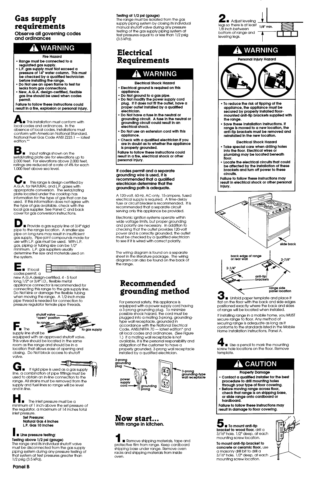
2 H Adjust leveling legs so there is at least l/8 inch between bottom of range and leveling legs.
Personal InJury Hazard
. To reduce the risk ot tlpplng ot the appliance, the appliance must be secured by properly Installed tloor- mounted antl-tlp brackets supplled wlth the range.
. Save these lnstallatlon Instructions. It range Is moved to a new location, the antl-tlp brackets must be removed and relnstalled In the new locatlon.
Electrlcal Shock Hazard
. Take special care when drllllng holes Into the tloor. Electrlcal wires or plumblng may be located beneath rloor.
l locate the electrlcal clrcults that could be affected by the lnstallatlon ot these brackets and turn otf power to these clrcults.
Failure to r0ii0w these lnstructlons may result In electrlcal shock or other personal InJury.
| | : |
back | edge of range | ) |
or rear | wall | |
w Unfold paper template and place it flat on the floor with the back and side edges positioned exactly where the back and sides of range will be located when installed.
If installing range in a mobile home, you MUST secure range to floor. Any method of securing range is adequate as long as it conforms to the standards listed in the Mobile Home Installation instructions, Panel A.
4 1 Use a pencil to mark the mounting screw hole locations on the floor. Remove template.
Property Damage
l Contact a qualltled Installer ror the best procedure to drill mountlng holes through your type ot tloor coverlng.
l Betore movlng range across tloor, check that range Is on shlpplng base, or slide range onto cardboard or hardboard.
Failure to tallow these lnstructlons may result In damage to tloor coverlng.
3 w To mount antl-tlp bracket to wood tloor, drill a 3/l 6” hole, 112” deep, at each mounting screw location.
To mount antl-tlp bracket to concrete or ceramic rloor, use a masonry drill bit to drill a
3/l 6” hole, 112” deep, at each mounting screw location.