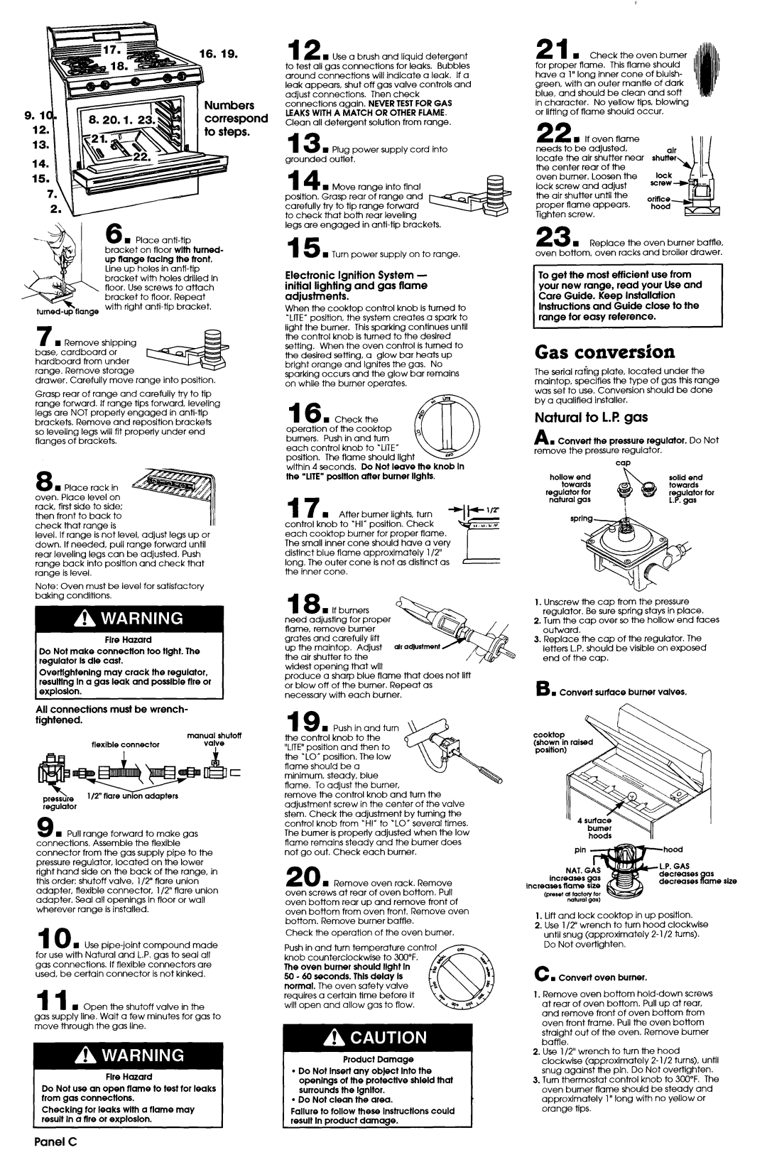
16. 19.
3 Numbers correspoi to steps.
6 n Place
bracket on floor wlth turned- up flange taclng the tront.
Line up holes in
12 w Use a brush and liauid detergent to test all gas connections for ‘leaks. Bubbles around connections will indicate a leak. If a leak appears, shut off gas valve controls and
adjust connections. Then check connections again. NEVERTESTFOR GAS LEAKSWITHA MATCH OR OTHERFLAME. Clean all detergent solution from range.
13 n Plug power supply cord into grounded outlet.
14cn Move range into final position. Grasp rear of range and carefully try to tip range forward to check that both rear leveling
legs are engaged in
15 n Turn power supply on to range.
Electronic Ignition System - initial lighting and gas flame adjustments.
When the cooktop control knob is turned to “LITE”position, the system creates a spark to
21 n Check the oven burner for proper flame. This flame should have a 1” long inner cone of bluish- green, with an outer mantle of dark blue, and should be clean and soft
in character. No yellow tips, blowing or lifting of flame should occur.
22 n If oven flame needs to be adjusted,
locate the air shutter near shutter the center rear of the
oven burner. Loosen the lock screw and adjust the air shutter until the proper flame appears. Tighten screw.
23 n Replace the oven burner baffle, oven bottom, oven racks and broiler drawer.
To get the most efficient use from your new range, read your Use and Care Guide. Keep Installation Instructions and Guide close to the range for easy reference.
7 n Remove shipping base, cardboard or hardboard from under range. Remove storage
drawer. Carefully move range into position.
Grasp rear of range and carefully try to tip range forward. If range tips forward, leveling legs are NOT properly engaged in
8n Place rack in oven. Place level on rack, first side to side; then front to back to check that range is
level. If range is not level, adjust legs up or down. If needed, pull range forward until rear leveling legs can be adjusted. Push range back into position and check that range is level.
Note: Oven must be level for satisfactory baking conditions.
Fire Hazard
Do Not make connection too tlght. The regulator Is die cast.
Overtlghtenlng may crack the regulator, resulting In a gas leak and possible fire or explosion.
All connections must be wrench- tightened.
| manual shutoff |
flexible connector | valve |
pressure l/2” flare union adapters regulator
9 n Pull range forward to make gas connections. Assemble the flexible - connector from the gas supply pipe to the pressure regulator, located on the lower right hand side on the back of the range, in this order: shutoff valve, l/2” flare union adapter, flexible connector, l/2” flare union adapter. Seal all openings in floor or wall wherever range is installed.
10 n Use
11 n Open the shutoff valve in the
gas supply line. Wait a few minutes for gas to move through the gas line.
Fire Hazard
Do Not use an open tlame to test tor leaks trom gas connectlons.
Checking tar leaks wlth a tlame may result In a fire or explosion.
light the burner. This sparking continues until the control knob is turned to the destred setting. When the oven control is turned to the desired setting, a glow bar heats up bright orange and Ignites the gas. No sparking occurs and the glow bar remains on while the burner operates.
16 n | Check | the |
|
| |
operation | of the cooktop | 3 |
| ||
burners, Push in and turn |
| ||||
|
| ||||
each control knob to “LITE” |
| ,a0 | |||
position. The flame | should Ilght w | ||||
| |||||
within 4 seconds, Do Not leave the knob In the ‘LITE” posltlon after burner Ilghts.
17 n After burner lights, turn control knob to ‘HI” position. Check each
distinct blue flame approximately l/2” long. The outer cone is not as distinct as the inner cone.
18 n If burners need adjusting for proper flame, remove burner grates and carefully lift up the maintop. Adjust the air shutter to the widest opening that will
produce a sharp blue flame that does not lift or blow off of the burner. Repeat as necessary with each burner.
19 H Push in and turn \ the control knob to the “LITE”position and then to
the “LO” position. The low flame should be a minimum, steady, blue flame. To adjust the burner,
remove the control knob and turn the adjustment screw in the center of the valve stem. Check the adjustment by turning the control knob from “HI” to ‘LO” several times. The burner is properly adjusted when the low flame remains steady and the burner does not go out. Check each burner.
20 w Remove oven rack. Remove oven screws at rear of oven bottom. Pull oven bottom rear up and remove front of oven bottom from oven front. Remove oven bottom. Remove burner baffle.
Check the operation of the oven burner.
Push in and turn temperature control
knob counterclockwise to 300°F. The oven burner should light In 50 - 60 seconds. Thls delay Is normal. The oven safety valve requires a certain time before it will open and allow gas to flow.
Product Damage
lDo Not Insert any object Into the openlngs ot the protective shield that surrounds the Ignltor.
lDo Not clean the area.
Failure to tallow these lnstructlons could result In product damage.
Gas conversion
The serial rating plate, located under the maintop, specifies the type of gas this range was set to use. Conversion should be done by a qualified installer.
Natural to 1.R gas
A I Convert the pressure regulator. Do Not
remove the pressure regulator.
|
| cap |
hollow | end | solid end |
towards | towards | |
regulator | for |
|
natural | gas |
|
1.Unscrew the cap from the pressure regulator. Be sure spring stays in place.
2.Turn the cap over so the hollow end faces outward.
3.Replace the cap of the regulator. The letters L.P. should be visible on exposed end of the cap.
6 . Convert surface burner valves.
cooktop
(shown in raised position)
hoods | II |
| |
incr | decreases | as | |
decreases | Pame size | ||
increases | |||
|
| ||
(preset |
|
|
1.Lift and lock
2.Use l/2” wrench to turn hood clockwise
until snug (approximately
C n Convert oven burner.
1.Remove oven bottom
2.Use l/2” wrench to turn the hood
clockwise (approximately 2- l/2 turns), until snug against the pin. Do Not overtighten.
3.Turn thermostat control knob to 3oo”F, The oven burner flame should be steady and
approximately 1” long with no yellow or orange tips.