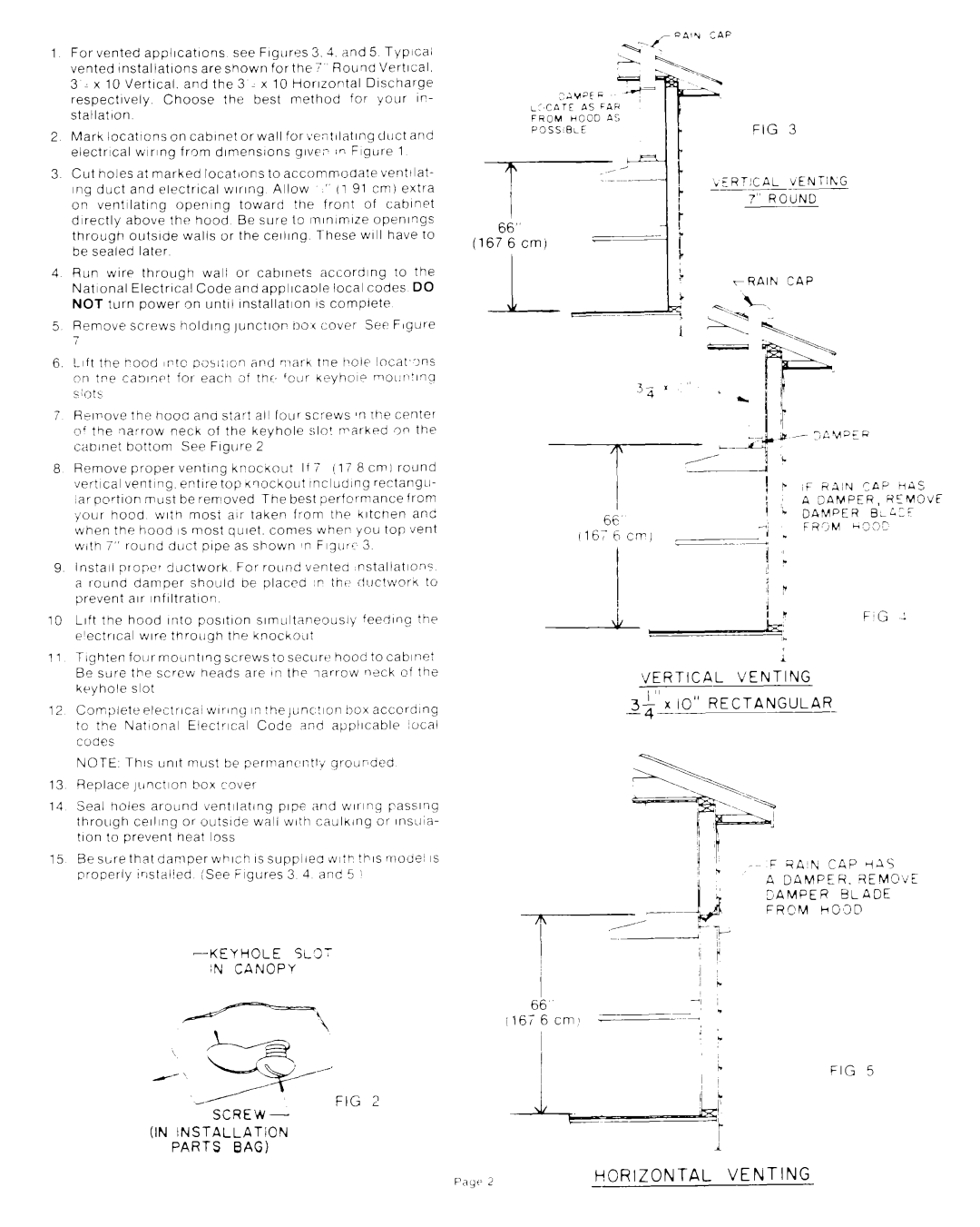
1 For vented appllcatlons see Flgllres 3. 3. And 5 Typica;
vented lnstallatlons areshown forthe Round Vertical.
3 : x 10 Vertical. and the 3 x 10 Horlzorltal Discharge
respectively Choose the best method for your IP- stallatlon
2 Mark locatIons on cabinet or wall for;,e:itllatlng duct and
electrIcal wiring from dlmenslons give:- in Figure 1
3 Cut holes at marked locatIons to accommodate venttlat-
mg duct and electrlcal wlrlng Allow ” (1 91 cm) extra
on ventilating opemng toward the front of cabinet directly above the hood Be sure to lnlnlmlze openlrlgs through outslde walls or the celling
4 Run wire through wali or cabinets according to the
National ElectrIcal Code and appllcaole local codes DO
NOT turn power on untW Installation IS complete
5 Remove screws holding )unctlor- noi cover Set Figure
6.
7 H;IVOV~ ?he hoot ana star? all foyer screws II rhe CPnter of the Iiarrow neck of the keyhole :;lo! rrarkpd ,on the cabinet bottom See Figure 2
8 | Remove | proper | venting | kpocitout |
| If | 7 | (17 | 8 cm1 | round | |||||||||
| \ier?ical | venting, | entire | top | Knockout |
| tncludlng | rectangle- | |||||||||||
| ,ar | portion | mast | be | rerrloved |
|
| The best | |||||||||||
| );our | hood |
| with | most | air | taken | from | the | kltcnen |
| and | |||||||
| when the hood IS most quiet. comes whep you top vent | ||||||||||||||||||
| with | 7” | round | dL)ct | pipe as | shown |
| #n F~qur’ | 3 |
|
| ||||||||
9 | Install | proper | :jLJCtwork | For |
| round | venteo | nstaltations | |||||||||||
| a | [round | damper | should | ne | placed |
| ,P | thi> | iiI.lctworn | to | ||||||||
| prevent | air | infIltratIon |
|
|
|
|
|
|
|
|
|
|
|
| ||||
10 | Lift | the | hood | Into | posItIon |
| slmclltaneously |
| feedIng | the | |||||||||
| e’ectrlcal | wire through | the | knockoLlt |
|
|
|
|
|
| |||||||||
11 | TIghten | four | moLlntlng | screws | to | securt’ | hood to cabirTn: | ||||||||||||
| Be | sure | the | screw | heads | are | in | the | larrow | r?;ck |
| of the | |||||||
| keyhole | slot |
|
|
|
|
|
|
|
|
|
|
|
|
|
| |||
12 | Completeelectrica~ |
|
| n?he~unc!ion | boxaccorolng | ||||||||||||||
| to | the | National | Elect~cal |
| Code |
| and | applicable |
| xxal | ||||||||
| Codes |
|
|
|
|
|
|
|
|
|
|
|
|
|
|
|
| ||
| NOTE | Th!s | umt | must | be | permani’r:tIY |
| qrourded |
|
| |||||||||
13 | Replace | jlinction | box | c‘over |
|
|
|
|
|
|
|
|
| ||||||
14 | Seal | holes | around | tientilating |
| pipe |
| and | wlrg | passl’ig | |||||||||
| through | ceiling | or | outslde |
| willi | with | caulking | or | InsLIla- | |||||||||
| tlon | to | prevent | heat | loss |
|
|
|
|
|
|
|
|
|
| ||||
15Be sLre that damper which IS suppiiec &I:P this niode! IS
properly lristalied iSee Figures 3 4 and 5 :
FIG ?
SCREW-
(IN iNSTALLATiON
PARTS BAG)
;ivat F
LCCATE AS FAH
FROM HCjOD A:
FIG 3
.ERTICAL VENTihG
7” ROilND
rRAlh CAP
i
VERTICAL VENTING
3$‘rio” RECTANGULAR-
FIG 5
